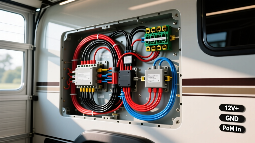
The Danger of Adapting Home Security Wiring to 12V Vehicles
When outfitting recreational vehicles, overland rigs, or fleet transports with high-definition surveillance, many DIYers and fleet technicians search for a Vivint camera install guide, attempting to repurpose premium home IP cameras for automotive use. While home security cameras offer superior resolution and cloud integration compared to standard 12V automotive backup cameras, attempting to wire residential Power over Ethernet (PoE) or 120V AC systems into a 12V DC vehicle architecture is a leading cause of electrical fires and destroyed control modules.
Automotive electrical systems operate on a strict 12V to 14.4V DC tolerance, subject to severe voltage spikes (load dump) and high-frequency vibration. Home IP cameras rely on 48V DC PoE or 120V AC adapters. Bridging this gap requires precise DC-DC step-up converters, automotive-grade wire insulation, and strict adherence to parasitic draw limits. Below, we detail the most catastrophic mistakes made during these cross-platform installs and provide the correct wiring schematics to execute them safely.
Top 4 Installation Mistakes & Safety Warnings
1. Bypassing the 48V PoE Requirement (Frying the Internal Buck Converter)
Most high-end smart home cameras utilize IEEE 802.3af Active PoE, expecting 48V DC delivered over the unused pairs of a Cat5e/Cat6 cable. A common mistake is attempting to wire a 12V RV battery directly into a passive PoE injector. Because the camera expects 48V, feeding it 12V will either result in a failure to boot or, worse, cause the camera's internal step-down regulator to draw excessive amperage, melting the RJ45 connector and creating a short circuit.
The Fix: You must use an isolated 12V DC to 48V DC PoE step-up injector. These automotive-grade boost converters accept 10-16V DC input and output a regulated 48V DC to the Ethernet cable.
2. Using THHN Residential Wire Instead of SAE GXL/TXL
Residential installers often use leftover THHN (Thermoplastic High Heat-resistant Nylon-coated) wire from home jobs. THHN is designed for stationary, climate-controlled environments inside PVC conduit. In an RV or fleet vehicle, THHN insulation quickly degrades when exposed to engine bay heat, UV rays, and constant chassis vibration. The rigid insulation cracks, exposing bare copper to the steel chassis and causing dead shorts.
The Fix: Only use SAE J1128 compliant GXL or TXL primary wire. These feature cross-linked polyethylene (XLPE) insulation that is highly resistant to heat, chemicals, and abrasion, and is specifically engineered for automotive harnesses.
3. Ignoring Parasitic Draw on the Chassis Battery
Smart cameras stay in 'standby' mode to detect motion and maintain Wi-Fi/cellular connections. A typical home IP camera draws between 3W and 6W continuously. If wired directly to a vehicle's starter battery without an ignition-sense relay or a low-voltage disconnect (LVD), the camera will drain the cranking battery in 48 to 72 hours, leaving the vehicle stranded.
The Fix: Wire the camera system to the RV's house battery bank via a dedicated DC distribution bus, or use an automotive smart relay that cuts power when the alternator voltage drops below 12.8V.
4. Improper Grounding via Self-Tapping Screws
Drilling into the vehicle chassis with a self-tapping sheet metal screw to establish a ground for a camera power supply introduces severe corrosion risks and high-resistance connections. Modern vehicles use advanced high-strength steel (AHSS) and aluminum alloys that do not self-tap cleanly, leading to micro-arcing and localized heat buildup.
The Fix: Use existing, factory-sealed chassis ground studs. If a new ground point is mandatory, drill a clean hole, apply an anti-corrosion compound, and secure an M6 or M8 ring terminal with a flange nut torqued to 10 Nm.
12V to 48V PoE Step-Up Wiring Pinout
If you are integrating a PoE IP camera into a 12V system, the step-up converter must be wired correctly to the Cat5e/6 Ethernet cable. Below is the standard passive PoE pinout used for 10/100 Base-T automotive network runs.
| RJ45 Pin | Wire Color (Cat5e) | Function | Step-Up Converter Terminal |
|---|---|---|---|
| Pin 1 | White/Orange | Data + | N/A (Data) |
| Pin 2 | Orange | Data - | N/A (Data) |
| Pin 3 | White/Green | Data + | N/A (Data) |
| Pin 4 | Blue | PoE Positive (+) | 48V OUT (+) |
| Pin 5 | White/Blue | PoE Positive (+) | 48V OUT (+) |
| Pin 6 | Green | Data - | N/A (Data) |
| Pin 7 | White/Brown | PoE Negative (-) | 48V OUT (-) |
| Pin 8 | Brown | PoE Negative (-) | 48V OUT (-) |
Wire Gauge & Voltage Drop Specification Chart
Running 12V DC to a step-up converter over long distances in a motorhome or trailer results in significant voltage drop. If the voltage at the input of the 48V boost converter drops below 10.5V, the converter will shut down or overheat. Calculate your wire gauge based on the total round-trip distance (positive and negative leads combined).
| Total Wire Run (Round Trip) | Camera Load (Watts) | Current Draw @ 12V | Minimum AWG (GXL Wire) | Expected Voltage Drop |
|---|---|---|---|---|
| 10 Feet | 10W | 0.83A | 18 AWG | 0.17V |
| 25 Feet | 10W | 0.83A | 16 AWG | 0.27V |
| 40 Feet | 15W | 1.25A | 14 AWG | 0.32V |
| 60 Feet | 15W | 1.25A | 12 AWG | 0.30V |
Note: Always size your inline fuse based on the wire gauge, not the load. A 14 AWG wire requires a maximum 15A fuse, but for a 1.25A camera load, use a 3A or 5A MINI blade fuse at the power source to protect the device.
Expert Troubleshooting: Symptom-Cause-Solution Matrix
When adapting residential tech to automotive environments, failures rarely mimic standard home networking issues. Use this diagnostic matrix to resolve common installation anomalies.
| Symptom | Root Cause | Expert Solution |
|---|---|---|
| Camera reboots randomly when vehicle engine is cranked. | Voltage sag during cranking drops below the step-up converter's low-voltage cutoff. | Install a 10,000µF automotive-grade capacitor in parallel with the 12V input, or wire to an isolated house battery with a DC-DC charger. |
| Ethernet link light is on, but camera fails to initialize. | Incorrect PoE pinout or using an unshielded RJ45 connector causing EMI interference from the alternator. | Verify Pins 4/5 (+) and 7/8 (-). Replace standard RJ45 ends with shielded, grounded Cat6 connectors to block alternator whine and EMI. |
| Step-up converter becomes too hot to touch. | Operating at the absolute minimum input voltage, forcing the converter to draw maximum amperage to maintain 48V output. | Upgrade wire gauge by two sizes (e.g., from 16 AWG to 12 AWG) to reduce resistance and voltage drop at the input terminals. |
| Vehicle BCM throws a U-code (Network Communication Fault). | Camera's unshielded data lines are routed parallel to the vehicle's CAN bus wiring, injecting noise into the network. | Reroute camera Ethernet cables at least 6 inches away from any twisted-pair CAN High/CAN Low wiring harnesses. |
Final Safety Directives for Automotive IP Integrations
Adapting a Vivint-style home security ecosystem into a mobile platform requires respecting the harsh realities of automotive electrical engineering. Never tap into airbag circuits, CAN bus lines, or safety-critical BCM modules to power auxiliary cameras. Always utilize an Add-a-Circuit fuse tap on a non-safety accessory circuit (like the radio or 12V cigarette lighter circuit), ensuring the tap is placed above the factory fuse to maintain the original circuit's protection.
Furthermore, ensure all exterior camera housings meet a minimum of IP67 ratings. Residential cameras are typically IP65, which is sufficient for rain but will fail when exposed to the high-pressure, high-temperature spray of an automated vehicle wash or the extreme thermal cycling of a highway environment. By adhering to SAE wiring standards and utilizing proper DC-DC isolation, you can safely achieve residential-grade surveillance on the road.