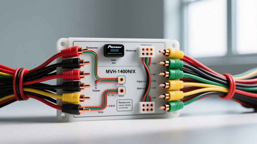
Pioneer MVH-1400NEX Backup Camera Installation: Technical Reference
The Pioneer MVH-1400NEX is a digital media receiver that supports NTSC composite video inputs for rearview camera integration. Unlike factory-integrated systems, aftermarket installations require precise voltage matching, impedance alignment, and electromagnetic interference (EMI) mitigation. This technical specification reference details the exact wiring parameters, signal tolerances, and circuit topologies required for a flawless Pioneer MVH-1400NEX backup camera installation.
Harness Pinout and Wire Gauge Specifications
The MVH-1400NEX utilizes Pioneer's standard 18-pin main harness. Proper integration of the reverse trigger and power delivery requires adherence to specific American Wire Gauge (AWG) standards to prevent voltage drop and signal latency.
| Function | Wire Color | AWG Size | Voltage/Spec |
|---|---|---|---|
| Battery Constant | Yellow | 18 AWG | 12V-14.4V DC |
| Ignition Switched | Red | 18 AWG | 12V-14.4V DC |
| Chassis Ground | Black | 18 AWG | 0V (Resistance < 0.2 ohms) |
| Reverse Trigger | Purple/White | 22 AWG | +6V to +12V DC Input |
Composite Video Signal and RCA Specifications
The camera input on the MVH-1400NEX is a single female RCA connector located on the rear chassis panel. The internal analog-to-digital converter (ADC) expects a standard NTSC composite video signal.
- Signal Type: NTSC Composite (CVBS)
- Resolution: 720 x 480 (interlaced)
- Signal Amplitude: 1.0V peak-to-peak (p-p)
- Impedance: 75 ohms
- Sync Level: -0.286V (Color Burst)
When routing the RCA cable from the rear hatch to the dashboard, maintain a minimum separation of 12 inches from high-current amplifier power wires (e.g., 4 AWG or 8 AWG main power lines). Parallel routing of RCA cables alongside 12V power lines induces alternator whine and horizontal rolling bars due to capacitive coupling. Reference the SAE J1113 Electromagnetic Compatibility standards for automotive cable routing best practices.
RCA Cable Selection and Signal Capacitance
Standard consumer-grade RCA cables often fail in automotive environments due to high capacitance and poor shielding. For runs exceeding 15 feet from the rear hatch to the MVH-1400NEX dashboard, signal degradation manifests as color bleeding or ghosting on the display. Use RG-59 or RG-6 coaxial cables terminated with high-quality RCA plugs. The dielectric material should be foam PE (polyethylene) to minimize capacitance (ideally < 20 pF/ft). Furthermore, ensure the RCA outer shield is grounded only at the head unit end (the MVH-1400NEX chassis ground) to prevent ground loops. Grounding both the camera end and the head unit end creates an antenna effect, picking up high-frequency EMI from the vehicle's ignition coils and fuel injectors.
Reverse Trigger Circuit and PWM Taillight Integration
The Purple/White wire on the Pioneer harness acts as the logic trigger. When it receives a positive voltage (+6V to +12V), the head unit interrupts the current audio source and switches the display to the RCA camera input.
The PWM Taillight Problem in Modern Vehicles
In vehicles manufactured after 2015 (particularly Chrysler, Dodge, Jeep, and Ford models), the reverse light circuit is often controlled by a Pulse Width Modulation (PWM) module rather than a direct 12V relay. A PWM signal rapidly pulses the voltage to extend bulb life and monitor for outages. If you tap the Pioneer Purple/White trigger wire directly into a PWM reverse light wire, the MVH-1400NEX will experience rapid flickering, failure to trigger, or display rolling interference lines.
Relay Bypass Topology
To resolve PWM interference, install a standard ISO 12V automotive relay (Bosch style, 30A) to isolate the camera power and trigger signal.
- Pin 86 (Coil +): Tap to the vehicle's reverse light PWM wire.
- Pin 85 (Coil -): Connect to a clean chassis ground.
- Pin 30 (Common): Connect to a dedicated 12V constant or switched fuse tap (10A).
- Pin 87 (Normally Open): Split this output. One line provides clean 12V DC to the camera's red power wire; the other line connects to the Pioneer MVH-1400NEX Purple/White reverse trigger wire.
This topology ensures the camera receives a steady 12V DC signal while providing a clean logic high to the Pioneer head unit. For additional filtering, a 1000µF 16V electrolytic capacitor can be soldered in parallel across the camera's power and ground wires at the rear hatch to smooth any residual voltage ripple.
Grounding Topologies and Chassis Preparation
A flawed ground is the leading cause of ground loop noise and camera failure. The MVH-1400NEX black ground wire must terminate to bare, unpainted sheet metal.
- Strip away any paint, clear coat, or rust using 80-grit sandpaper or a rotary wire brush.
- Apply a dielectric grease over the bare metal after securing the ring terminal to prevent oxidation while maintaining conductivity.
- Use a self-tapping sheet metal screw or an existing M6 factory bolt. Torque to 8-10 Nm to ensure high-pressure contact.
- Verify the ground with a multimeter; resistance between the head unit ground and the vehicle battery negative terminal must read less than 0.2 ohms.
For comprehensive installation examples and vehicle-specific harness adapters, consult resources like Crutchfield's backup camera integration guides, which provide model-specific trim removal and wire routing diagrams.
CMOS vs. CCD Sensor Power Draw Considerations
When selecting a camera for the MVH-1400NEX, understand the power draw differences between CMOS and CCD sensors. Most modern aftermarket backup cameras utilize CMOS sensors due to their low power consumption (typically 80mA to 120mA at 12V). CCD sensors, while offering superior low-light performance and wider dynamic range, can draw upwards of 250mA to 300mA. If you are tapping the reverse light circuit directly without a relay (only recommended for pre-2015 vehicles with non-PWM analog circuits), ensure the vehicle's reverse light fuse (usually 10A or 15A) can handle the combined load of the incandescent bulbs and the camera. Upgrading to LED reverse bulbs lowers the circuit load, safely allowing a direct CCD camera tap without blowing the BCM (Body Control Module) fuse.
Troubleshooting Signal Degradation
If the Pioneer MVH-1400NEX displays a 'No Signal' message or a blue/black screen when shifted into reverse, follow this diagnostic sequence:
- Verify Trigger Voltage: Use a digital multimeter (DMM) to probe the Purple/White wire at the back of the head unit. It must read a steady +12V DC when the vehicle is in reverse. If it reads 0V, check the relay Pin 87 connection.
- Check RCA Continuity: Disconnect the RCA cable. Use the continuity setting on your DMM to test the center pin (signal) and outer barrel (ground) for shorts. A reading near 0 ohms indicates a crushed or pinched RCA cable, usually occurring in the rubber weather boot between the chassis and the liftgate.
- Test Camera Power: Measure voltage at the camera's pigtail harness. NTSC cameras require a minimum of 5.5V DC to operate, though 12V is standard. If voltage drops below 5V under load, the power wire gauge is too thin or the ground is compromised.
Proper execution of these technical specifications ensures that your Pioneer MVH-1400NEX backup camera installation operates with factory-level reliability, free from EMI, voltage drops, and trigger latency. Always reference the official Pioneer Car Electronics documentation for firmware updates that may affect camera switching logic and display grid overlays.