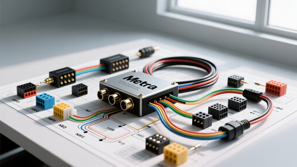
Understanding the Metra RCA Converter Wiring Diagram
Integrating aftermarket amplifiers, DSPs, or camera-triggered audio processors into a vehicle with a factory head unit requires stepping down high-level speaker signals to low-level RCA pre-amp signals. The metra rca converter wiring diagram serves as the foundational blueprint for this integration. Whether you are utilizing a passive step-down transformer model or an active solid-state Line Output Converter (LOC) like the Axxess AX-LOC (Metra's premium integration brand), understanding the exact pinouts, wire gauge requirements, and signal flow is critical to avoiding alternator whine, signal clipping, and ground loops.
This comprehensive guide approaches the installation from a Cost & Tool Requirements Analysis perspective. We will break down exactly what you need to buy, the true cost of doing the job correctly versus taking dangerous shortcuts, and the professional-grade tools required for a permanent, OEM-quality connection.
Factory Speaker Input (Primary Side)
The primary side of the Metra LOC connects to the vehicle's factory speaker harness. For this analysis, we will reference the common 2014-2018 GM Silverado/Sierra platform (non-Bose), which is a frequent candidate for LOC integration.
- Front Left (+): Tan (18 AWG)
- Front Left (-): Gray (18 AWG)
- Front Right (+): Light Green (18 AWG)
- Front Right (-): Dark Green (18 AWG)
According to the SAE J1128 Primary Cable Standard, 18 AWG wire is sufficient for signal-level speaker inputs drawing less than 3 amps, but upgrading to 16 AWG oxygen-free copper (OFC) for the LOC input pigtails reduces resistance and preserves transient response.
RCA Output, Power, and Remote Turn-On (Secondary Side)
The secondary side outputs the low-level signal and manages the LOC's internal switching circuitry.
- Power (B+): 18 AWG Red wire. Must be connected to a fused 12V constant source or tapped into the factory radio's constant 12V memory wire (usually Yellow or Orange).
- Ground (GND): 18 AWG Black wire. Must be terminated to a bare metal chassis point using an M6 ring terminal, torqued to 8-10 Nm.
- Remote Out: 18 AWG Blue/White wire. Outputs a +12V, 300mA trigger signal to turn on your aftermarket amplifier when the factory radio detects audio.
- RCA Outputs: Shielded twisted-pair cables. Keep these physically separated from the B+ and speaker inputs by at least 18 inches to prevent electromagnetic interference (EMI).
Tool Requirements Analysis: Professional vs. DIY
The most common point of failure in any car audio or camera-tech installation is a poor physical connection. Relying on cheap tools leads to stranded wire damage, cold solder joints, and eventual signal degradation. Below is an analysis of the tooling required for a permanent Metra LOC installation.
| Tool Category | Budget / DIY Option | Professional / Recommended Option | Why the Pro Tool Matters |
|---|---|---|---|
| Wire Strippers | Generic hardware store crimpers ($12) | Knipex MultiStrip 10 or Titan 1105 ($45-$85) | Prevents nicking the copper strands of 18 AWG wire, which reduces ampacity and causes hotspots. |
| Soldering Station | 40W Unregulated Iron ($15) | Hakko FX888D or Pinecil V2 ($30-$100) | Provides stable 350°C heat for 60/40 rosin-core solder, ensuring capillary action into the wire strands without melting the PVC jacket. |
| Testing Equipment | 12V Test Light ($5) | Fluke 115 True RMS Multimeter ($250) | Test lights draw current and can trigger airbag modules or fry CAN-bus lines. A DMM safely verifies AC speaker voltage and DC remote triggers. |
| Signal Verification | Smartphone Mic App (Free) | SMD DD-1 Distortion Detector ($100) | Accurately identifies the exact factory volume knob position where the radio's internal amp begins to clip (usually around volume 28-32). |
Material Cost Breakdown: Doing It Right the First Time
When analyzing the metra rca converter wiring diagram for a project budget, installers often focus solely on the cost of the LOC itself. However, the termination materials dictate the longevity of the system. T-taps (scotch locks) pierce the wire insulation, exposing bare copper to moisture and oxidation, leading to high-resistance failures within 12 to 18 months. Below is a comparative Bill of Materials (BOM) for a 2-channel LOC installation.
Cost Comparison Chart
| Component | The 'Cheap' Method (High Failure Rate) | The 'OEM-Spec' Method (Permanent) |
|---|---|---|
| Metra / Axxess LOC Unit | $15.00 (Passive 2-Ch) | $35.00 (Active AX-LOC) |
| Wire Taps / Connectors | $4.00 (T-Taps & Butt Crimps) | $14.00 (Posi-Taps & Solder Sleeves) |
| Terminal & Grounding | $2.00 (Self-tapping screw) | $6.00 (M6 Ring Terminal, Zinc Flange Nut, Anti-Corrosion Gel) |
| Wire & Shielding | $5.00 (CCA 18 AWG Kit) | $18.00 (OFC 16 AWG + Techflex Braided Sleeving) |
| RCA Cables | $10.00 (Unshielded molded RCA) | $30.00 (Twisted-Pair Shielded RCA) |
| Total Material Cost | $36.00 | $103.00 |
While the OEM-spec method costs roughly $67 more, it eliminates the need for future diagnostic teardowns. As noted in Crutchfield's comprehensive LOC installation guides, investing in active LOCs and shielded cabling is mandatory for modern vehicles with complex multiplexed wiring and high-noise alternators.
Step-by-Step Soldering and Integration Protocols
To execute the wiring diagram flawlessly, follow these professional integration steps:
- Disconnect the Battery: Always isolate the negative battery terminal (10mm or 13mm, depending on the vehicle) and wait 10 minutes for SRS capacitors to discharge before tapping into the factory harness.
- Locate and Verify Signals: Use your True RMS Multimeter set to AC Voltage (V~). Play a 50Hz test tone through the factory radio. Probe the suspected speaker wires. You should read between 2V and 8V AC depending on the volume level. Confirm polarity by ensuring the positive wire reads a positive DC offset relative to chassis ground during the initial transient.
- Prepare the Pigtails: Strip 3/8 inch of insulation from the 16 AWG OFC pigtails and the factory harness. Apply a small amount of water-soluble flux.
- Solder and Seal: Tin both wires separately, then join them using a Western Union splice. Apply 60/40 rosin-core solder until it wicks completely through the strands. Cover with 3:1 ratio adhesive-lined marine heat shrink and apply heat until the sealant purges from the ends.
- Establish a Star Ground: The Metra LOC ground must share the same ground node as the aftermarket amplifier it is feeding. This creates a 'star ground' topology, preventing ground loop currents from flowing through the RCA shields, which manifests as alternator whine that pitches up and down with engine RPM.
Troubleshooting: Whine, Clipping, and Signal Loss
Even with a perfect physical execution of the metra rca converter wiring diagram, active and passive LOCs require precise tuning.
Setting the Gain Potentiometer
Active Metra LOCs feature internal gain dials. If set too high, the LOC will amplify the factory radio's inherent noise floor and clipping distortion. Use a Digital Multimeter to measure the AC voltage at the RCA outputs while playing a 0dBFS 1kHz test tone. Adjust the LOC's potentiometer using a plastic jeweler's screwdriver until the RCA output reads between 2.0V and 4.0V RMS. Do not exceed 5.0V, as most aftermarket amplifier input stages will clip.
Dealing with Factory Bass Roll-Off
Many modern factory radios (especially GM, Ford, and FCA/Stellantis) employ speed-sensitive volume and bass roll-off EQ curves. As you turn the volume up, the factory amp cuts bass frequencies to protect cheap paper speakers. If your aftermarket subwoofer seems to get quieter as the volume goes up, the passive Metra LOC is accurately passing this crippled signal. The solution is to upgrade to an active LOC with a built-in Bass Restoration Circuit (like the Axxess AX-LOC or an AudioControl LC2i), which uses a 12V trigger to synthesize and inject the missing sub-bass frequencies back into the RCA signal path.
Authoritative References
- Metra Electronics Technical Bulletins & Integration Guides - Official documentation for Axxess and Metra LOC pinouts and load requirements.
- SAE J1128: Low Tension Primary Cable Standard - Society of Automotive Engineers specifications for wire gauge, insulation thickness, and thermal ratings in automotive environments.
- Crutchfield Car Audio Learning Center - Industry-standard best practices for line output converter placement, grounding, and signal routing.