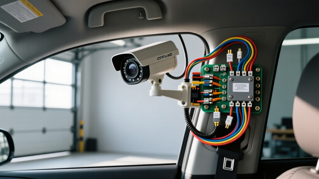
Automotive CCTV Troubleshooting: Master Flow Guide
Heavy-duty commercial fleets, RVs, and horse trailers increasingly rely on automotive-grade surveillance systems to eliminate blind spots and monitor cargo. However, a flawed closed-circuit television camera installation often results in severe voltage drop, electromagnetic interference (EMI), or ground loops. Unlike residential security cameras that run on regulated 120V AC or PoE (Power over Ethernet), mobile CCTV systems must survive the harsh, electrically noisy environment of a 12V/24V DC vehicle chassis.
This guide provides a step-by-step troubleshooting decision tree for master technicians diagnosing post-installation failures in 4-pin aviation and RCA-based mobile CCTV systems.
Baseline Specification: 4-Pin Aviation (GX16) Connector Pinout
Before troubleshooting, verify your physical layer matches industry standards. Most commercial fleet and RV CCTV systems utilize a 4-pin GX16 aviation connector. Incorrect pinning is the leading cause of immediate monitor failure.
| Pin | Function | Wire Color (Standard) | Recommended AWG / Type |
|---|---|---|---|
| 1 | VCC (12V DC Power) | Red | 14 AWG TXL (Cross-linked) |
| 2 | GND (Chassis Ground) | Black | 14 AWG TXL |
| 3 | Video Signal (Coax Core) | Yellow (Shielded) | 18 AWG RG178 Coaxial |
| 4 | Audio / IR Trigger | White or Blue | 18 AWG Shielded |
Note: Always use TXL or GXL automotive wire for power runs. Standard PVC THHN wire will melt and short out when routed near exhaust components or engine bays.
Decision Tree 1: Monitor Displays 'No Signal' or Blank Screen
Symptom: The monitor powers on, but the camera feed is entirely black or displays a 'No Signal' overlay.
Step 1: Verify Source Voltage Under Load
Do not test voltage at the battery. Test voltage at the camera pigtail while the system is connected and drawing current. Mobile CCTV cameras with infrared (IR) arrays can pull up to 2.5A upon startup. If your 18 AWG wire run exceeds 12 feet, voltage drop will starve the camera.
- Target Metric: Minimum 11.5V DC at the camera pins with the engine running.
- Fix: If voltage reads below 11.0V, upgrade the VCC and GND lines to 12 AWG. Use the voltage drop formula:
V_drop = (2 x Length x Current x Resistance_per_1000ft) / 1000.
Step 2: Isolate the Reverse Trigger Circuit (PWM Interference)
Modern trucks (e.g., 2015+ Ford F-150, Ram 2500) use Pulse Width Modulation (PWM) to control backup lamps. Tapping a CCTV reverse trigger directly into a PWM-controlled reverse light circuit will confuse the monitor's logic board, causing it to reject the video signal.
- Diagnostic Test: Connect an oscilloscope or a digital multimeter with a min/max hold function to the trigger wire. If you see rapid fluctuations between 0V and 12V instead of a steady 12V, you have PWM interference.
- Fix: Install a PAC TR-4 trigger module or a standard Bosch-style 30A relay. Use the PWM reverse light circuit only to trigger the relay coil (Pins 85/86), and pull the monitor's 12V trigger from a clean, fused ignition-switched upfitter circuit via the relay's switched contacts (Pins 30/87).
Decision Tree 2: Flickering Video, 'Rolling Bars', or Alternator Whine
Symptom: The video feed displays horizontal rolling lines, flickers when the turn signals activate, or emits a high-pitched whine through the audio channel.
Step 1: Identify the Ground Loop
Ground loops occur when the camera and the monitor are grounded to different points on the chassis that have varying electrical potentials. The video signal uses the chassis ground as a reference; if the ground potential fluctuates, the monitor interprets it as video noise.
- Diagnostic Test: With the engine running and accessories on, measure the AC voltage between the camera's ground pin and the monitor's ground pin using a multimeter set to AC Volts. Any reading above 0.05V AC indicates a ground loop.
- Fix: Implement a single-point 'Star Ground' topology. Run a dedicated 14 AWG ground wire from the camera all the way back to the monitor's ground point, bypassing the chassis entirely. Alternatively, install a 12V DC ground loop isolator on the coaxial video line.
Step 2: Shielding and EMI Routing (SAE J1113 Compliance)
According to SAE J1113 standards for electromagnetic compatibility, unshielded signal wires routed parallel to high-current cables will induce severe noise.
- Cause: Routing the RG178 video cable in the same wire loom as LED light bar relays, air compressor power lines, or ABS sensor wiring.
- Fix: Maintain a minimum 6-inch separation between CCTV coaxial cables and high-amperage DC power lines. If crossing is unavoidable, cross them at a strict 90-degree angle. Verify that the copper braided shield of the coaxial cable is properly soldered to Pin 2 (Ground) at both the camera and monitor ends.
Decision Tree 3: Infrared (IR) Night Vision Fails to Engage
Symptom: The camera works perfectly during daylight, but the IR LEDs fail to illuminate at night, leaving the screen pitch black.
Step 1: Test the Photoresistor (CdS Cell)
Automotive CCTV cameras utilize a Cadmium Sulfide (CdS) photoresistor to detect ambient light levels and trigger the IR relay.
- Diagnostic Test: Cover the camera lens and photoresistor completely with a dark cloth. Listen closely to the camera housing. You should hear a distinct 'click' from the internal micro-relay engaging the IR array. If no click is heard, the sensor is blocked by debris, or the internal relay has failed.
- Fix: Clean the sensor dome with isopropyl alcohol. If the relay clicks but the LEDs remain dark, proceed to Step 2.
Step 2: Calculate IR Array Current Starvation
When IR LEDs activate, the camera's current draw spikes from roughly 0.3A (daytime) to 1.5A - 2.5A (nighttime). If the power wire is undersized, the voltage drops below the 10.5V threshold required to fire the IR diodes.
- Diagnostic Test: Measure the voltage at the camera's VCC pin while the lens is covered and the IR array is attempting to draw power.
- Fix: If voltage drops below 10.8V under IR load, the wire gauge is insufficient for the distance. The National Truck Equipment Association (NTEA) upfitter guidelines strongly recommend oversizing power conductors for high-draw auxiliary equipment. Upgrade the power feed to 12 AWG and ensure the inline fuse is rated for at least 5A (fast-blow) per camera.
Environmental Sealing and Connector Integrity
Mobile environments subject connections to extreme thermal cycling, road salt, and high-pressure car washes. A perfect electrical diagnosis means nothing if moisture breaches the connector.
- Heat Shrink Protocol: Never use standard vinyl electrical tape for exterior camera pigtails. Use 3M MDT (Medium Dual Wall) adhesive-lined heat shrink tubing. The inner meltable adhesive creates a waterproof mechanical seal that blocks capillary action.
- Dielectric Grease Application: Apply a liberal amount of silicone dielectric grease to the threads and pin faces of the GX16 aviation connector before mating. This prevents galvanic corrosion between dissimilar metals and ensures the O-ring seats properly against moisture ingress.
- Drip Loops: When mounting the camera to the exterior of an RV or trailer, always route the cable in a 'U' shaped drip loop below the entry hole before feeding it through the bulkhead. This prevents water from tracking down the cable jacket and directly into the interior wall cavity.
Advanced Diagnostic Tools for Fleet Technicians
For large-scale commercial fleet deployments, relying on a standard multimeter is insufficient. Master technicians should utilize a portable CCTV field monitor with a built-in PTZ (Pan-Tilt-Zoom) controller and a 12V DC output. This allows you to power and test the camera directly at the rear of a 53-foot trailer, isolating the camera hardware from the vehicle's internal wiring harness. Additionally, a Time Domain Reflectometer (TDR) can be used on long coaxial runs to pinpoint the exact distance of a crushed or shorted video cable inside a sealed wall cavity.
By adhering to this structured troubleshooting flow, technicians can eliminate guesswork, ensure compliance with Mobile Electronics Association best practices, and deliver a closed-circuit television camera installation that withstands the rigors of the road.