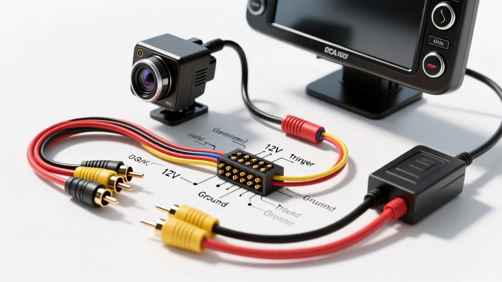
Introduction to Aftermarket Reverse Camera Integration
A successful car reverse camera installation requires more than simply routing a cable from the trunk to the dashboard. Modern vehicle electrical systems utilize complex CAN-bus networks, Pulse Width Modulation (PWM) for lighting circuits, and strict electromagnetic compatibility (EMC) standards. Furthermore, the shift from standard CVBS (Composite Video Blanking and Sync) to AHD (Analog High Definition) means installers must verify protocol compatibility before making a single connection. This comprehensive guide details the exact wiring schematics, wire gauge requirements, and relay bypass techniques necessary for a flawless aftermarket backup camera integration.
Signal Protocols: CVBS vs. AHD Cameras
Before routing wires, verify the video signal protocol of your camera and head unit. Standard RCA cables carry analog video, but the encoding differs:
- CVBS (NTSC/PAL): Outputs 480i/576i resolution. Compatible with 95% of legacy and budget aftermarket head units. Uses standard 75-ohm impedance RCA cables.
- AHD (720p/1080p): Outputs high-definition analog video over the same RCA connector. Warning: If you connect an AHD camera to a CVBS-only head unit, the screen will remain black or display a rolling, distorted image. Ensure your head unit explicitly supports AHD input in its hidden factory settings menu.
Required Tools and Wire Specifications
Using the correct wire gauge and connection hardware prevents voltage drop and signal degradation. Refer to the specification chart below for your installation:
| Component | Specification | Installation Notes |
|---|---|---|
| Video Cable | Shielded 75-Ohm RCA | Must have integrated 18 AWG trigger wire. Avoid running parallel to amplifier power cables to prevent EMI. |
| 12V Power/Trigger Wire | 18 AWG Stranded Copper | Sufficient for the low amperage draw (typically <250mA) of CMOS/CCD cameras. |
| Ground Connection | 18 AWG with Ring Terminal | Must connect to bare, unpainted chassis metal. Do not use self-tapping screws into sheet metal if a factory bolt is available. |
| Wire Connectors | Posi-Tap or Solder/Heat Shrink | Never use standard T-Taps or ScotchLoks; they cause micro-fractures in low-gauge automotive wiring and invite corrosion. |
| Relay (For PWM Vehicles) | Bosch-style 5-Pin 12V DC | Required for late-model VW, Audi, BMW, and Ford vehicles using PWM taillights. |
Step 1: Routing the RCA Video and Trigger Cable
The path you choose for the RCA cable dictates the long-term reliability of your video signal. According to SAE J1113 standards for electromagnetic compatibility, low-voltage video signals are highly susceptible to alternator whine and ignition interference.
- Remove Interior Trim: Carefully pry up the door sill plates, kick panels, and trunk trim. Use a nylon trim removal tool to avoid snapping brittle plastic clips.
- Follow the Factory Harness: Route the RCA cable along the factory wiring loom on the passenger side of the vehicle. This side typically houses fewer high-current accessory wires compared to the driver's side.
- Avoid Heat and Pinch Points: Keep the cable at least 6 inches away from the exhaust system heat shields. When passing through the firewall or trunk grommet, use a blunt awl to pierce the rubber, and seal the puncture with marine-grade silicone to prevent carbon monoxide and water intrusion.
- Airbag Deployment Zones: Never route cables across the A-pillars or C-pillars where side-curtain airbags deploy. Always route wiring behind the airbag curtain, securing it with zip ties to the factory metal brackets.
Step 2: Tapping the Reverse Light Circuit (12V Power)
The camera requires a 12V DC power source that only activates when the vehicle is shifted into reverse. While tapping the reverse light bulb socket seems logical, modern vehicle lighting systems complicate this process.
Identifying the Reverse Lamp Wire
Use a digital multimeter (DMM) to probe the wires at the taillight assembly. Have an assistant shift the vehicle into reverse (with the engine off and ignition in the 'ON' position). The correct wire will show +12V to +14.4V. Mark this wire using masking tape.
The PWM Problem and the Relay Bypass Solution
Many modern European and domestic vehicles use Pulse Width Modulation (PWM) to control taillight brightness and monitor bulb health. Instead of a steady 12V DC, a PWM circuit rapidly pulses the voltage (often between 6V and 11V at frequencies of 500Hz to 2kHz). If you wire a backup camera directly to a PWM circuit, the camera will flicker violently, display a 'No Signal' error, or fail to power on entirely.
The Solution: 12V Stabilizer Relay Bypass
To bypass the PWM signal, use the factory reverse light wire only as a trigger for a standard 12V automotive relay, pulling steady power from a dedicated ignition source.
- Pin 86 (Relay Coil +): Connect to the factory PWM Reverse Light Wire.
- Pin 85 (Relay Coil -): Connect to a clean chassis ground.
- Pin 30 (Common Power In): Connect to a fused 12V ignition-on source (e.g., cigarette lighter circuit or fuse box add-a-circuit).
- Pin 87 (Normally Open Output): Connect to the Red +12V power wire on the camera harness.
This setup ensures the camera receives a clean, unfiltered 12V DC signal, completely eliminating flickering and protecting the camera's internal voltage regulator.
Step 3: Head Unit Wiring and Reverse Trigger Input
For the head unit to automatically switch to the camera view when shifted into reverse, it requires a +12V trigger signal. This is often the most misunderstood part of a car reverse camera installation. The RCA cable's integrated 'pigtail' wire must be connected to the specific reverse trigger wire on the aftermarket head unit's harness.
Common aftermarket head unit reverse trigger wire colors include:
- Pioneer: Purple/White stripe (labeled 'Reverse' or 'Back')
- Kenwood / JVC: Orange/White stripe
- Alpine: Orange (Solid)
- Sony: Orange/White stripe
Crucial Note: Do not confuse the camera's RCA trigger pigtail with the head unit's 'Amp Turn-On' (Blue/White) wire. Connecting the camera trigger to the Amp Turn-On wire will force the camera onto the screen whenever the stereo is on, or cause the head unit to reboot due to back-feeding voltage.
Connect the RCA pigtail wire at the dashboard to the head unit's reverse wire using a Posi-Tap. At the trunk, connect the camera's red +12V wire to the reverse light circuit (or the relay bypass described above). Do not connect the RCA pigtail wire at the trunk; it must only receive power from the head unit's low-amperage trigger output to activate the screen switching relay inside the stereo.
Troubleshooting Common Signal and Power Failures
Even with meticulous planning, installations can present unique electrical gremlins. Use this diagnostic matrix to resolve common issues:
| Symptom | Probable Cause | Corrective Action |
|---|---|---|
| Black Screen / 'No Signal' | AHD/CVBS mismatch, or no 12V power to camera. | Verify head unit AHD settings. Check 18 AWG power wire at the camera pigtail with a DMM while in reverse. |
| Image Flickering or Rolling | PWM voltage on the reverse light circuit. | Install the 5-pin relay bypass module to supply steady 12V DC from an ignition source. |
| Alternator Whine in Audio | Ground loop or RCA routed near power cables. | Ensure camera ground is on bare metal. Reroute RCA cable away from amplifier 4-AWG power wires. |
| Image is Mirrored/Flipped | Camera loop-back wire cut/connected incorrectly. | Locate the small white/green loop wire on the camera pigtail. Cut or join it to toggle between front/rear view orientation. |
| Head Unit Doesn't Auto-Switch | Trigger wire connected to Amp Turn-On (Blue/White). | Move the RCA pigtail wire to the correct Purple/White or Orange/White reverse trigger wire on the head unit harness. |
Authoritative References and Best Practices
Proper automotive electrical integration requires adherence to industry standards. The procedures outlined in this guide align with the best practices established by the Mobile Electronics Certification Professional (MECP) program, specifically regarding wire termination and current load management. For further reading on vehicle-specific wiring schematics and CAN-bus lighting architectures, consult the Crutchfield Car Stereo Reverse Wire Guide, which maintains an up-to-date database of OEM trigger wire colors and PWM requirements for late-model vehicles. Always disconnect the negative battery terminal before splicing into any factory lighting circuits to prevent shorting the vehicle's Body Control Module (BCM).