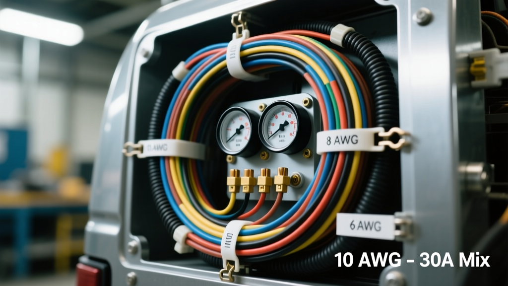
The 30-Amp Automotive Circuit: Why Wire Gauge Matters
When building, upgrading, or repairing high-draw automotive accessories, the most common question we receive from technicians and DIYers is: what gauge wire for 30 amp circuits is required to ensure safety and optimal performance? The short answer is that 10 AWG (American Wire Gauge) is the industry standard for 30-amp chassis wiring in 12V DC automotive systems, provided the total circuit length (positive and ground combined) does not exceed 15 to 20 feet. However, if the wire run extends to the rear of a long-bed truck or a trailer bumper, or if the wire is routed through high-ambient-temperature zones like an engine bay, stepping up to 8 AWG is mandatory to mitigate voltage drop and prevent thermal degradation.
Undersized wiring on a 30-amp circuit doesn't just cause accessories to underperform; it creates a severe fire hazard. A 30-amp draw pushing through a bottleneck of 12 AWG or 14 AWG wire generates immense resistive heat. This heat melts connector housings, degrades insulation, and ultimately leads to dead shorts. In this guide, we will break down the exact specifications for 30-amp circuits and provide a step-by-step troubleshooting flow to diagnose and repair failing high-amperage automotive circuits.
Reference Chart: What Gauge Wire for 30 Amp Applications?
The following specification chart is based on the SAE J1128 Standard for Low Tension Primary Cable, which governs automotive wiring. Unlike household AC wiring (governed by the NEC), automotive DC wiring requires stricter voltage drop tolerances due to the low baseline voltage of a 12V system.
| AWG Size | Max Ampacity (Chassis) | Resistance (Ohms/1000ft @ 20°C) | Best Automotive 30A Use Case |
|---|---|---|---|
| 8 AWG | 40 - 50 Amps | 0.6282 Ω | Long runs (15ft+), Engine bay routing, Winches, High-draw inverters |
| 10 AWG | 30 Amps | 0.9989 Ω | Standard chassis runs, Cooling fans, Fuel pumps, Trailer brake controllers |
| 12 AWG | 20 Amps | 1.588 Ω | NOT RATED FOR 30A - Will cause voltage drop and melted terminals |
Step-by-Step Troubleshooting Flow: Diagnosing a Failing 30A Circuit
When a 30-amp accessory (such as an auxiliary transmission cooler fan or an electric trailer brake system) begins to fail intermittently, the root cause is frequently a hidden wiring bottleneck. Follow this diagnostic decision tree to isolate the fault.
Step 1: Visual Inspection & Thermal Damage Check
- Symptom: Accessory cuts out under heavy load or after running for 5-10 minutes.
- Action: Inspect all inline fuse holders, relays, and connector housings. Look for brown discoloration on plastic housings or a 'sweet' burnt smell.
- Specific Check: If using an Aptiv Metri-Pack 280 series connector, check the female terminal cavity. Heat from undersized wire (e.g., 12 AWG feeding a 30A relay) will cause the terminal to lose tension, creating micro-arcing.
- Fix: If the plastic housing is warped or the terminal is loose, cut back to clean, un-oxidized copper and replace the connector.
Step 2: Voltage Drop Testing (The 0.5V Rule)
According to standard automotive electrical diagnostics, a healthy 12V circuit should never experience a voltage drop greater than 0.5V across the entire positive side, or 0.1V across the ground side.
- Setup: Set your digital multimeter (DMM) to DC Volts. Connect the red probe to the positive battery terminal and the black probe to the power input pin at the accessory.
- Load the Circuit: Turn the accessory ON. For a cooling fan, ensure it is fully engaged. For a trailer brake controller, manually apply the slide bar to maximum output.
- Read the Drop: If your DMM reads 1.2V or higher, you have excessive resistance. This is the definitive proof that the wire gauge is too small for the 30-amp draw, or there is severe corrosion at a crimp joint.
Step 3: Amperage Verification via Hall-Effect Clamp
- Action: Clamp a DC-compatible Hall-effect ammeter around the primary positive wire.
- Analysis: If the accessory is rated for 30 amps but is only pulling 22 amps while under full load, the undersized wire is choking the current flow. The wire is acting as a resistor, dropping the voltage reaching the motor or solenoid, which in turn lowers the amperage draw and performance.
Real-World Case Study: Ford F-Series Trailer Brake Controller
A frequent victim of the 'what gauge wire for 30 amp' confusion is the aftermarket trailer brake controller circuit. In late-model Ford F-150 and F-250 trucks equipped with a factory 7-way RV blade connector, Pin 2 (the Blue wire) is dedicated to the electric trailer brakes. This circuit is protected by a 30-amp fuse in the Battery Junction Box (BJB).
The Failure Mode: Many DIYers install aftermarket brake controllers using pre-made 12 AWG pigtails because they are cheaper and easier to route through the firewall. When towing a heavy 3-axle trailer, the brake controller attempts to push 25-30 amps through the 12 AWG wire. The resulting voltage drop starves the trailer brakes, leading to dangerous sway conditions. Furthermore, the heat generated often melts the 7-way connector on the bumper.
The Expert Fix: Always verify that the blue wire feeding Pin 2 is a minimum of 10 AWG. If you are extending the factory harness to a custom rear bumper, upgrade the extension to 8 AWG Blue wire to account for the added length, ensuring maximum braking voltage reaches the trailer's magnet drums. For more on standard trailer pinouts, refer to the etrailer.com 7-Way Wiring FAQ.
The Math Behind the Gauge: Calculating Voltage Drop
To understand exactly why 10 AWG is the minimum for 30 amps, we use the automotive voltage drop formula:
VD = (2 x L x R x I) / 1000
- VD = Voltage Drop
- L = One-way length of the wire in feet
- R = Resistance per 1000ft of the wire (from SAE J1128 charts)
- I = Current in Amps (30A)
If you run 10 feet of 10 AWG wire (R = 0.9989) at 30 Amps:
VD = (2 x 10 x 0.9989 x 30) / 1000 = 0.59V.
This is borderline acceptable. If you increase the length to 15 feet, the drop exceeds 0.8V, which will noticeably dim lights or slow down electric motors. By upgrading to 8 AWG (R = 0.6282) for a 15-foot run:
VD = (2 x 15 x 0.6282 x 30) / 1000 = 0.56V, keeping the circuit safe and efficient.
Corrective Action: Terminating 10 AWG Wire for High-Vibration Environments
Selecting the correct gauge is only half the battle. A 30-amp circuit will still fail if the termination method is inadequate. Standard open-barrel 'F-crimps' commonly used in low-draw sensor circuits are insufficient for 10 AWG power wires subjected to chassis vibration.
- Strip the Wire: Use a precision wire stripper to remove exactly 5/16' of insulation from the 10 AWG wire. Do not nick the copper strands, as this creates a localized stress fracture and a future heat point.
- Select the Terminal: Use a closed-barrel, adhesive-lined ring terminal sized for an M8 (5/16') stud.
- Crimp Tooling: Use a dedicated closed-barrel crimping tool (such as a TE Connectivity AMP or equivalent heavy-duty ratcheting crimper). The crimp should deform the barrel into a hexagonal or quad-point shape, ensuring cold-welding of the copper strands.
- Seal and Shrink: Apply heat evenly using a heat gun set to 300°F (150°C) until the adhesive lining oozes slightly from the edges of the heat shrink tubing. This prevents moisture ingress and capillary action wicking.
- Torque Specification: When securing the M8 ring terminal to the chassis ground or power distribution stud, torque the flange nut to 10 - 12 Nm (7.4 - 8.8 lb-ft). Under-torquing leads to micro-arcing and melted studs; over-torquing can snap the stud or crush the terminal barrel.
Summary: Sizing for Safety and Reliability
When determining what gauge wire for 30 amp circuits, never compromise on copper cross-section. Stick to 10 AWG for short, cabin-routed runs, and confidently step up to 8 AWG for engine bays and long chassis runs. By following the voltage drop testing procedures and utilizing proper closed-barrel terminations, you will eliminate the most common causes of high-amperage electrical failures in modern vehicles. For further reading on automotive cable insulation standards and temperature ratings, consult the NFPA 70 National Electrical Code Article 310 for baseline ampacity comparisons, while always deferring to SAE standards for under-hood vehicle applications.