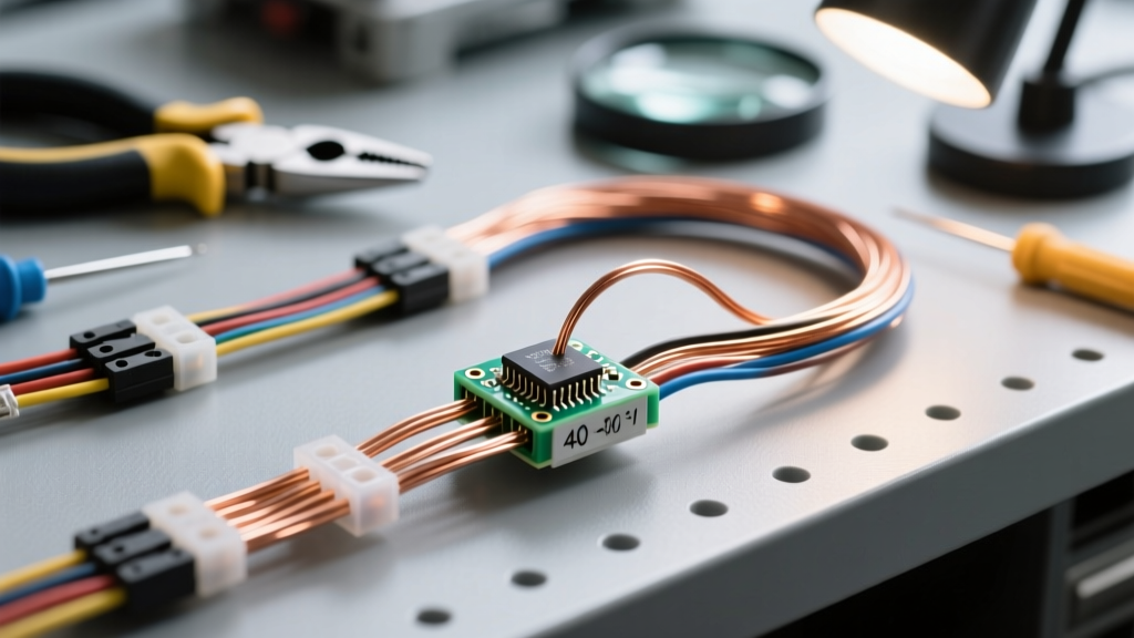
The Critical Role of 40 AWG in Modern Automotive Diagnostics
When diagnosing complex Controller Area Network (CAN) faults, piezoelectric injector waveforms, or delicate thermocouple circuits, standard automotive wire gauges are entirely inadequate. Enter super fine 40 gauge copper wire. At just 0.0031 inches (0.0799 mm) in diameter, 40 AWG is significantly thinner than a human hair. While it has virtually zero ampacity for power transmission (maxing out around 0.024 amps), it is the undisputed king of high-fidelity signal probing, micro-sensor coil winding, and ECU printed circuit board (PCB) trace repair.
Modern automotive diagnostics rely heavily on oscilloscopes to visualize sensor behavior. However, accessing these signals without damaging the wiring harness requires extreme precision. This practical guide details the exact methodology for fabricating, installing, and utilizing 40 AWG copper wire for non-destructive ECU micro-probing and fine sensor repairs.
Technical Specifications: 40 AWG vs. Standard Probe Wire
Understanding the physical and electrical limitations of 40 AWG is critical before applying it to any vehicle. Because of its high resistance per foot, it must only be used for high-impedance voltage reference and signal probing, never for current-carrying circuits.
| Specification | 40 AWG Copper (Signal Probe) | 24 AWG Copper (Standard T-Pin) | 18 AWG Copper (Standard Harness) |
|---|---|---|---|
| Diameter (Inches) | 0.00314" | 0.0201" | 0.0403" |
| Diameter (mm) | 0.0799 mm | 0.511 mm | 1.024 mm |
| Cross-Sectional Area | 0.0050 mm² | 0.205 mm² | 0.823 mm² |
| Resistance (@ 20°C) | 1,079 Ω / 1000 ft | 25.67 Ω / 1000 ft | 6.38 Ω / 1000 ft |
| Max Ampacity (Chassis) | 0.024 A (Signal Only) | 3.5 A | 16 A |
| Primary Automotive Use | ECU Micro-Probing, PCB Repair | Back-probing older connectors | 12V Sensors, Injector Power |
Why Standard T-Pins Destroy Modern ECU Connectors
A common and catastrophic mistake made by novice technicians is using standard 22 or 24 AWG steel T-pins to back-probe modern ECU connectors. Modern engine management systems utilize high-density TE Connectivity or Molex connectors with 0.64mm (and increasingly 0.50mm) female terminal cavities.
The beryllium copper tension fingers inside a 0.64mm female terminal are engineered to grip a 0.64mm male tab with a specific insertion and extraction force. Forcing a 0.511mm (24 AWG) steel T-pin into this cavity permanently yields and spreads the tension fingers. When the T-pin is removed, the female terminal no longer exerts adequate clamping force on the male ECU pin. This results in a high-resistance connection, micro-arcing, and intermittent sensor dropouts that are notoriously difficult to diagnose. By fabricating custom micro-probes using super fine 40 gauge copper wire, the wire slips past the tension fingers without causing any mechanical deformation, preserving the integrity of the harness. For more on proper terminal retention and probing techniques, refer to the Pico Technology Oscilloscope Probing Guide.
Essential Tooling for 40 AWG Micro-Wire Installation
Working with 40 AWG wire requires specialized micro-electronics tooling. Standard automotive wire strippers and soldering irons will instantly destroy the wire.
- Thermal Wire Stripper: Mechanical strippers will snap 40 AWG. A thermal stripper (hot tweezer) melts the insulation (typically polyurethane or polyimide) without nicking the microscopic copper core.
- Stereo Microscope: A 10x to 40x magnification boom microscope is mandatory for visual verification of solder joints and terminal insertion.
- Micro-Soldering Station: A temperature-controlled micro-pencil iron (e.g., Hakko FX-951) with a 0.5mm conical tip, set to exactly 300°C (572°F).
- Ultra-Fine Solder: 63/37 Tin/Lead rosin-core solder wire with a diameter of 0.015" (0.38mm). Lead-free solder requires higher temperatures that risk melting the 40 AWG core.
- Tacky Flux: A no-clean, high-tack rosin flux pen to prevent the microscopic wire from balling up or oxidizing during tinning.
Step-by-Step Guide: Fabricating 40 AWG ECU Micro-Probes
This procedure outlines how to create a flexible, non-destructive back-probe lead that connects a 0.64mm ECU connector to a standard 4mm banana plug for oscilloscope testing.
Step 1: Prepping and Stripping the 40 AWG Wire
Cut a 12-inch length of 40 AWG enameled or polyurethane-coated copper wire. Using the thermal stripper set to 280°C, clamp the tip of the wire for 3 seconds to melt back exactly 1/8" of insulation. Gently wipe away the melted residue with a lint-free swab and isopropyl alcohol. Do not scrape the wire with a blade; the core will shear instantly.
Step 2: Micro-Tinning the Core
Apply a microscopic dab of tacky flux to the exposed 1/8" copper tip. Touch the 0.015" solder to the tip of your 300°C micro-pencil iron, then briefly touch the iron to the fluxed 40 AWG wire. The solder will instantly wick up the microscopic strands via capillary action. The tinned section should look shiny and uniform, with no visible frayed strands.
Step 3: Attaching the 4mm Banana Plug
At the opposite end of the 12-inch wire, strip 1/4" of insulation. Solder this end to the internal micro-solder cup of a high-quality 4mm shielded banana plug. Because the solder cup is massive compared to the 40 AWG wire, pre-tin the cup first, insert the wire, and apply heat for no more than 1.5 seconds to prevent the solder from wicking too far up the probe wire, which would make it stiff and brittle.
Step 4: Non-Destructive Terminal Insertion
Under the microscope, identify the target cavity on the TE Connectivity 0.64mm connector. Gently feed the un-tinned, bare 40 AWG tip into the rear wire-seal area of the female terminal, sliding it alongside the existing 20-22 AWG harness wire until it makes contact with the internal male ECU pin. The 0.0799mm wire will easily bypass the terminal tension fingers and the rear silicone weather seal without compromising the IP67 waterproof rating of the connector.
Step 5: Strain Relief and Securing
Once the signal is verified on the oscilloscope, secure the 40 AWG wire to the harness branch using a small piece of Kapton tape or a micro-drop of cyanoacrylate (CA) glue on the outside of the connector boot. Never apply CA glue directly to the terminal cavity, as capillary action will draw the glue into the contact interface, causing an open circuit.
Step-by-Step Guide: Micro-Soldering 40 AWG to Sensor Coils
Beyond probing, 40 AWG copper wire is frequently used to repair fine pickup coils, such as Variable Reluctance (VR) crankshaft sensors or internal ignition coil primary windings where trace breaks occur.
- Locate the Break: Use a digital multimeter in resistance mode to find the open circuit on the sensor PCB or coil bobbin.
- Clean the Pad: Under magnification, clean the copper trace or coil winding termination with a fiberglass scratch pen.
- Bridge with 40 AWG: Cut a 5mm piece of 40 AWG wire. Tack-solder one end to the source pad using 0.015" solder and a 0.5mm iron tip.
- Complete the Circuit: Lay the 40 AWG wire across the broken gap. Apply a microscopic drop of flux to the destination pad. Touch the iron to the pad and wire simultaneously. The thermal mass of the 40 AWG is so low that the heat transfers instantly; remove the iron the millisecond the solder flows.
- Conformal Coating: Once the repair is verified, encapsulate the 40 AWG jumper in UV-curable conformal coating to protect it from engine bay vibrations and moisture ingress. Refer to IPC J-STD-001 Standards for acceptable micro-soldering criteria in high-vibration environments.
Troubleshooting Decision Tree: 40 AWG Signal Loss
When using super fine 40 gauge copper wire for diagnostics, signal degradation or total loss can occur if the installation is flawed. Use this decision tree to isolate the fault:
- Symptom: Oscilloscope shows a flatline (0V) on a known active 5V reference circuit.
- Cause 1: The 40 AWG wire has sheared inside the insulation near the connector boot due to lack of strain relief.
Fix: Perform a continuity test from the banana plug to the terminal entry point. If open, fabricate a new probe with improved Kapton tape strain relief. - Cause 2: The wire failed to bypass the rear silicone weather seal and is resting on the rubber, not the metal terminal.
Fix: Retract the wire, use a micro-pick to gently lift the weather seal lip, and re-insert the 40 AWG wire directly into the terminal cavity.
- Cause 1: The 40 AWG wire has sheared inside the insulation near the connector boot due to lack of strain relief.
- Symptom: Waveform shows excessive high-frequency noise or alternator whine.
- Cause: 40 AWG wire has virtually no self-shielding and acts as an antenna for electromagnetic interference (EMI) from ignition coils and injectors.
Fix: Transition to a shielded 40 AWG micro-coaxial probe wire, or wrap the 40 AWG probe lead in copper foil tape grounded to the oscilloscope BNC shield.
- Cause: 40 AWG wire has virtually no self-shielding and acts as an antenna for electromagnetic interference (EMI) from ignition coils and injectors.
- Symptom: Solder joint at the banana plug appears dull, crystalline, and fractures easily.
- Cause: Cold solder joint caused by insufficient heat transfer into the massive 4mm brass plug, or movement during cooling.
Fix: Desolder the joint, clean with brass wick, pre-tin the plug cup, and re-solder using a higher-wattage micro-iron to ensure rapid thermal saturation.
- Cause: Cold solder joint caused by insufficient heat transfer into the massive 4mm brass plug, or movement during cooling.
Authoritative References and Connector Data
For detailed terminal cavity dimensions and insertion force specifications regarding the 0.64mm and 0.50mm connectors commonly probed with 40 AWG wire, technicians should consult the TE Connectivity Automotive 0.64mm Connector Catalog. Adhering to strict micro-probing protocols ensures that diagnostic procedures do not inadvertently create the very electrical faults the technician is trying to solve.