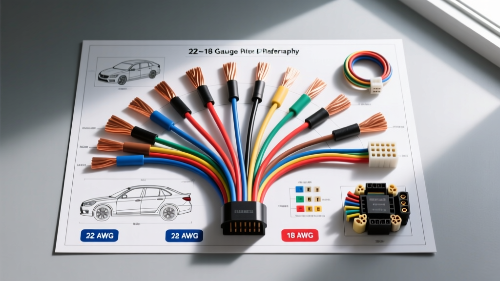
Introduction to Low-Current Automotive Circuits
When building, repairing, or extending an engine management harness, selecting the correct cross-sectional area for your conductors is non-negotiable. While high-current circuits like fuel pumps, starter solenoids, and cooling fans demand 12 to 10 AWG wiring, the vast majority of a modern Engine Control Unit's (ECU) inputs and outputs rely on much smaller conductors. Understanding the 22 18 gauge wire size spectrum is essential for anyone working with automotive sensors, low-current solenoids, and data buses. This guide provides a complete wiring diagram walkthrough focusing on the most common application for this wire range: the 4-wire heated oxygen (O2) sensor.
Why 22 to 18 AWG is the Standard for ECU Sensors
The phrase "22 18 gauge wire size" refers to the critical range of conductors used for low-amperage signaling and moderate-amperage actuator circuits. In a typical engine bay harness, 18 AWG is the workhorse for components that draw between 1 and 5 amps, such as sensor heaters, idle air control (IAC) valves, and low-impedance fuel injectors. Conversely, 22 AWG is reserved almost exclusively for high-impedance signal wires, such as thermistors (coolant and intake air temperature sensors), throttle position sensors (TPS), and O2 signal feedback loops.
Ampacity and Voltage Drop Considerations
According to SAE J1128 standards for low-tension primary cable, the ampacity of a wire is heavily dependent on its insulation material (e.g., XLPE vs. PVC) and ambient temperature. However, in automotive 12V systems, voltage drop is often a more limiting factor than thermal melting.
- 18 AWG Wire: Features a cross-sectional area of approximately 0.82 mm² and a resistance of 6.385 ohms per 1,000 feet. Over a standard 10-foot harness run carrying 4 amps (typical for an O2 heater circuit), the voltage drop is a negligible 0.25V.
- 22 AWG Wire: Features a cross-sectional area of 0.32 mm² and a resistance of 16.14 ohms per 1,000 feet. Because signal circuits draw milliamps (typically under 0.05A), the voltage drop over the same 10-foot run is a microscopic 0.008V, preserving the millivolt-level accuracy required by the ECU's analog-to-digital converters.
Complete Wiring Diagram Walkthrough: Heated O2 Sensor (4-Wire)
To understand how the 22 18 gauge wire size range is applied in the real world, let us walk through the wiring diagram of a standard 4-wire narrowband oxygen sensor, a component found on nearly every gasoline vehicle from the mid-1990s to today. The sensor requires four distinct circuits: two for the internal heating element and two for the zirconia signal generator.
Pinout and Wire Color Breakdown
The following table outlines a typical General Motors (LS-based) 4-wire O2 sensor pinout. Note how the 18 AWG wire is strictly utilized for the high-current heater circuit, while the 22 AWG wire handles the delicate signal return.
| Connector Pin | Function | Wire Size (AWG) | Typical GM/LS Color | Circuit Resistance / Load |
|---|---|---|---|---|
| Pin A | Heater 12V Supply (Ignition Switched) | 18 AWG | White | 2.0 - 4.5 Ohms (Heater Element) |
| Pin B | Heater Ground (ECU Controlled PWM) | 18 AWG | White/Black Stripe | Less than 0.5 Ohms (Harness) |
| Pin C | Signal Output (to ECU) | 22 AWG | Purple | High Impedance (100k+ Ohms) |
| Pin D | Signal Ground (Dedicated ECU Sensor Ground) | 22 AWG | Purple/White Stripe | Less than 0.1 Ohms (Harness) |
Diagram Narrative: How the ECU Reads the Circuit
When the ignition is turned on, the ECU monitors the engine coolant temperature. If the engine is cold, the ECU pulses the ground on Pin B (18 AWG) using Pulse Width Modulation (PWM) to gradually heat the zirconia element without thermal-shocking the ceramic. Once the sensor reaches roughly 600°F (315°C), the ECU begins reading the voltage differential between Pin C and Pin D (both 22 AWG). The 22 AWG wire size is critical here; using a thicker wire like 16 AWG for the signal would introduce unnecessary parasitic capacitance and stiffness, making the harness difficult to route and potentially degrading the high-frequency analog signal.
Connector Types and Terminal Crimping Specifications
Wire gauge is only half the battle; the terminal crimp is where most automotive electrical failures occur. For the 22 18 gauge wire size range, the industry standard connector is the Delphi (Aptiv) Metri-Pack 150.2 Series. This connector system utilizes a pull-to-seat design, meaning the wire seal is placed on the wire before the terminal is crimped, and the terminal is then pulled back into the connector housing until the plastic tang locks.
Terminal Selection and Crimp Tooling
Using the correct terminal for your specific AWG is mandatory. An 18 AWG terminal will not grip the copper strands of a 22 AWG wire securely, leading to arcing and voltage drops.
- For 18 AWG (Heater Circuit): Use Delphi terminal part number 12045773. This terminal features a larger wire barrel designed to crimp 0.50 - 0.80 mm² conductors. Use an open-barrel crimping tool with a 1.5mm² die.
- For 22 AWG (Signal Circuit): Use Delphi terminal part number 12045771. The wire barrel is significantly smaller, designed for 0.22 - 0.35 mm² conductors. Use a 0.6mm² die on your open-barrel crimper.
As noted in Haynes Automotive Wiring Basics, a proper open-barrel crimp should exhibit a slight "bell mouth" at the rear of the terminal, allowing you to visually verify that all copper strands are captured within the crimp wings without the insulation being pinched by the copper grips.
Troubleshooting 22-18 AWG Sensor Harnesses
When diagnosing sensor faults, technicians often make critical errors that permanently damage the 22 18 gauge wire size conductors. Because these wires are thin, they are highly susceptible to mechanical and thermal failure modes.
Common Failure Modes and Diagnostic Rules
- The Piercing Probe Mistake: Never use a standard multimeter probe to pierce the insulation of a 22 AWG signal wire to check for voltage. Piercing severs individual copper strands, creating a bottleneck that increases resistance. Worse, it creates a microscopic hole where moisture enters, leading to capillary corrosion that will eventually turn the copper into green oxide and cause an open circuit. Solution: Always use specialized T-pin back-probes inserted into the rear of the connector.
- Exhaust Manifold Chafing: 18 AWG heater wires are often routed near exhaust manifolds. If the corrugated split-loom degrades, the wire can rest against the cast iron. The high ambient heat melts the XLPE insulation, shorting the 12V heater circuit to the chassis ground. This will immediately blow the ECU's internal injector/sensor driver fuse or destroy the ECU's high-side driver transistor.
- Signal Ground Contamination: The 22 AWG signal ground (Pin D) must return directly to the ECU's dedicated analog ground plane. If a previous technician spliced this 22 AWG wire into a heavy 12 AWG chassis ground (like the alternator bracket), the ECU will read the alternator's AC ripple voltage. This results in a "noisy" O2 signal, causing the ECU to constantly hunt for the correct air/fuel ratio, leading to poor fuel economy and surging idle.
SAE Standards and Reference Charts
Adhering to established engineering standards ensures reliability in harsh under-hood environments. When sourcing wire for your 22 18 gauge wire size projects, always look for specifications that meet or exceed SAE J1128 (Low Tension Primary Cable) or ISO 6722-1. These standards dictate not only the copper stranding (typically 19 to 41 strands for flexibility) but also the insulation's resistance to battery acid, brake fluid, and 150°C thermal spikes.
Quick Reference: 22 vs 20 vs 18 AWG
| AWG Size | Metric Equivalent | Copper Diameter (in) | Max Chassis Amps (Single) | Primary Automotive Use Case |
|---|---|---|---|---|
| 18 AWG | 0.82 mm² | 0.0403 | 16A | Sensor heaters, IAC valves, small solenoids |
| 20 AWG | 0.52 mm² | 0.0319 | 11A | CAN bus networks, low-current LED markers |
| 22 AWG | 0.32 mm² | 0.0253 | 7A | Thermistors, TPS signals, O2 feedback loops |
By respecting the distinct roles of 18 AWG for power delivery and 22 AWG for signal integrity, you ensure that your engine management system receives clean, accurate data, resulting in optimal performance and long-term reliability.