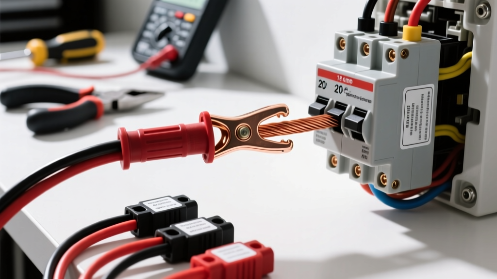
The AC vs. DC Paradox: Why 14 AWG on a 20A Breaker is Safe in Vehicles
If you show a residential electrician a 12-volt automotive wiring diagram that pairs 14 gauge wire with a 20 amp breaker, they will likely tell you it is a severe fire hazard. Under the National Electrical Code (NEC) for household AC wiring, 14 AWG copper is strictly limited to 15 amps, and using a 20A breaker violates NEC Article 240.4. However, automotive and marine DC electrical systems operate under entirely different physics, environmental conditions, and engineering standards.
In a 12V or 24V automotive DC system, running 14 gauge wire on a 20 amp breaker is not only common but completely safe, provided you are using the correct insulation type and adhering to maximum run lengths. The key differences lie in the insulation temperature ratings, the absence of alternating current skin effect, and the typically short wire runs found in engine bays and chassis routing. This guide provides a master-level installation protocol for deploying 14 AWG wire protected by a 20A circuit breaker in high-demand automotive applications, such as auxiliary EFI fuel pumps, winch solenoid triggers, and high-output lighting relays.
SAE J1128 Specs: Why Automotive 14 AWG Handles 20 Amps
The primary reason 14 gauge wire can safely carry 20 amps in a vehicle comes down to insulation chemistry. Residential wire (like THHN) uses PVC insulation rated for 90°C. In contrast, automotive primary wire must meet the SAE J1128 Standard for Low Tension Primary Cable.
When selecting your 14 AWG wire for a 20A circuit, you must avoid standard PVC jacketed wire. Instead, specify GXL or TXL wire. These variants utilize Cross-Linked Polyethylene (XLPE) insulation. XLPE is rated for continuous operation at 125°C (257°F) and can withstand engine bay ambient temperatures that would melt standard PVC and cause a short circuit. Because XLPE dissipates heat more efficiently and resists thermal degradation, a 14 AWG GXL wire has an open-air ampacity rating of approximately 25 to 30 amps, making a 20A breaker the perfect overcurrent protection device to prevent the wire from exceeding its thermal limits.
Voltage Drop and Maximum Run Lengths
While 14 AWG can handle the heat of 20 amps, the real enemy in 12V DC systems is voltage drop. Unlike 120V AC systems where a 5% voltage drop is barely noticeable, a 5% drop in a 12V automotive system means your 13.8V alternator output drops to 13.1V, which can cause sensitive ECU components or fuel pumps to underperform.
According to the Waytek Wire Sizing Chart and standard automotive engineering practices, a 3% voltage drop is the maximum acceptable threshold for non-critical circuits, and 1% is preferred for critical engine management circuits. Below is the voltage drop matrix for 14 AWG copper wire pushing a continuous 20-amp load.
| Wire Length (One Way) | Total Loop Resistance | Voltage Drop @ 20A | Percentage Drop (12V Nominal) | Acceptability |
|---|---|---|---|---|
| 5 Feet | 0.0127 Ω | 0.25V | 2.1% | Excellent |
| 10 Feet | 0.0255 Ω | 0.51V | 4.25% | Acceptable (Auxiliary Loads) |
| 15 Feet | 0.0382 Ω | 0.76V | 6.3% | Marginal (Max Limit for Lights) |
| 20 Feet | 0.0510 Ω | 1.02V | 8.5% | Fail (Step up to 12 AWG) |
Note: Wire length refers to the distance from the power source to the load. The total loop resistance accounts for both the positive and ground paths.
Step-by-Step Installation Guide: 20A Auxiliary Fuel Pump Circuit
For this installation protocol, we are wiring a high-pressure auxiliary fuel pump (e.g., Walbro 450 or Aeromotive) located in the rear of the vehicle, requiring a 15-foot run from the engine bay relay to the rear-mounted pump.
Step 1: Selecting the Breaker and Wire
Because the fuel pump draws 15 amps continuously but experiences an inrush current spike of up to 22 amps upon startup, a standard fast-acting thermal breaker will nuisance-trip. Select a 20A slow-blow (time-delay) thermal circuit breaker or a marine-rated resettable breaker. Ensure your wire is 14 AWG GXL with a minimum strand count of 41 for optimal flexibility and vibration resistance.
Step 2: Power Source and Breaker Placement
Connect the 14 AWG power feed directly to the battery's positive terminal or a high-amperage distribution busbar. The Blue Sea Systems Circuit Protection Guide and ABYC standards dictate that overcurrent protection must be installed within 7 inches of the power source. Mount your 20A breaker as close to the battery terminal as physically possible. If the wire between the battery and the breaker shorts to the chassis, it is entirely unprotected and can cause an unextinguishable electrical fire.
Step 3: Routing and Looming
Route the 14 AWG wire along the factory chassis harness, securing it every 18 inches with UV-resistant zip ties or Tesa tape. Keep the wire at least 4 inches away from exhaust components. Even though GXL insulation is rated for 125°C, exhaust manifolds can exceed 400°C, which will cause thermal derating. Thermal derating reduces the wire's ampacity; at 100°C ambient heat, your 14 AWG wire's safe capacity drops closer to 15 amps, meaning a 20A load will overheat the copper core.
Step 4: Termination and Crimping
Never solder automotive wire; solder joints wick moisture via capillary action and become brittle under chassis vibration. Instead, use 16-14 AWG heat-shrink ring terminals (typically color-coded blue). Use a ratcheting crimper to apply a uniform hex or indent crimp. After crimping, apply heat with a heat gun until the adhesive-lined polyolefin tubing melts and seals the wire barrel, preventing galvanic corrosion.
Real-World Troubleshooting: Voltage Drop & Thermal Failures
Even with perfect installation planning, 14 gauge wire on a 20 amp breaker can present unique diagnostic challenges. Use this decision tree to troubleshoot common field failures.
Symptom: Breaker Trips Intermittently Under Heavy Load
- Root Cause A: The ground path is corroded. A poor ground increases total circuit resistance, forcing the fuel pump motor to pull higher amperage to compensate for the voltage drop, eventually tripping the 20A breaker.
- Root Cause B: Thermal derating. The wire is routed too close to a catalytic converter or exhaust manifold, reducing its ampacity below 20A.
- Diagnostic Fix: Perform a voltage drop test on the ground side of the circuit while the pump is running. A reading above 0.1V indicates a bad ground. Reroute the wire away from heat sources if ambient temperatures exceed 80°C.
Symptom: Melted Terminal Insulation at the Load Connection
- Root Cause: High resistance at the crimp joint. This is almost always caused by using non-ratcheting pliers to crimp the terminal, or by stripping back too much insulation and leaving exposed copper outside the terminal barrel.
- Diagnostic Fix: Cut back the damaged wire. Strip exactly 3/8" of GXL insulation. Use a calibrated ratcheting crimper to attach a new adhesive-lined heat shrink terminal. Verify the pull-test strength by giving the wire a firm tug; a proper 14 AWG crimp should withstand over 30 lbs of pull force before failing.
Symptom: Fuel Pump Whines or Runs Sluggishly
- Root Cause: Excessive voltage drop due to exceeding the 15-foot maximum run length for 14 AWG at 20 amps. The pump is receiving less than 11.5V, causing it to lose flow rate and overheat internally.
- Diagnostic Fix: Measure voltage directly at the pump terminals with the engine running. If voltage is below 12.0V, you must upgrade the entire positive and negative run to 12 AWG or 10 AWG wire to reduce resistance.