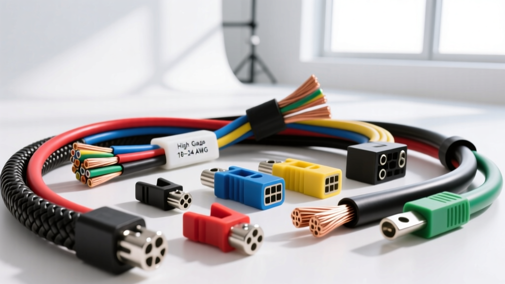
The 'High Gauge' Misconception: Understanding the AWG Inverse Scale
In automotive electrical diagnostics, the term high gauge wire is frequently misused by novices to describe thick, high-current battery cables. In reality, the American Wire Gauge (AWG) system is an inverse logarithmic scale. A 'high gauge' refers to a higher AWG number, which corresponds to a physically thinner wire with a smaller cross-sectional area. Therefore, when an automotive electrical engineer or master technician references high gauge wire, they are specifically talking about 18 AWG, 20 AWG, 22 AWG, and 24 AWG conductors.
These thin conductors are the central nervous system of modern vehicles. While low gauge (thick) wires carry the heavy current required for starters, alternators, and EV traction inverters, high gauge wires are strictly reserved for low-current, high-fidelity signal transmission, multiplex network communication, and sensitive sensor feedback loops. Misapplying wire sizing or failing to respect the strict SAE J1128 Low Tension Primary Cable specifications for these circuits will result in catastrophic data corruption, electromagnetic interference (EMI), and phantom diagnostic trouble codes (DTCs).
High Gauge Wire (18-24 AWG) Technical Specifications
The following reference chart details the physical and electrical properties of high gauge automotive primary wire, assuming standard stranded copper construction with cross-linked polyethylene (XLPE) or PVC insulation as outlined by SAE standards.
| AWG Size | Nominal Diameter (in) | Copper Area (CMA) | Resistance (Ω/1000ft @ 20°C) | Max Ampacity (Chassis Wiring) | Primary Automotive Application |
|---|---|---|---|---|---|
| 18 AWG | 0.0403 | 1,624 | 6.38 Ω | 16 Amps | Sensor heaters, low-draw solenoids, lighting |
| 20 AWG | 0.0320 | 1,022 | 10.15 Ω | 11 Amps | O2 sensor signals, injector triggers, CAN bus |
| 22 AWG | 0.0253 | 642 | 16.14 Ω | 7 Amps | MAF signals, CKP/CMP sensors, GMLAN |
| 24 AWG | 0.0201 | 404 | 25.67 Ω | 3.5 Amps | Thermistors, low-level audio, airbag squibs |
Note: Ampacity ratings for chassis wiring assume single conductors in free air. When bundled in tight automotive looms, thermal derating must be applied, reducing safe current capacity by up to 30%.
Critical Automotive Applications for Thin Signal Wires
1. CAN Bus and Multiplex Networks (ISO 11898-2)
Controller Area Network (CAN) protocols rely entirely on high gauge twisted-pair wiring to transmit differential voltage signals. High Speed CAN (HS-CAN) typically utilizes 20 AWG or 22 AWG stranded copper. The physical layer requires the CAN High (CAN H) and CAN Low (CAN L) wires to be twisted at a precise rate—usually between 3 to 5 twists per inch—to cancel out external electromagnetic interference.
- OBD-II Standard Pinout: Pin 6 (CAN H) and Pin 14 (CAN L) at the Data Link Connector (DLC) are universally reserved for HS-CAN. Wire colors vary by OEM, but commonly feature a base color with a tracer stripe (e.g., Ford MS-CAN often uses White/Blue and White/Brown).
- Termination: The network requires exactly two 120-ohm termination resistors placed at the extreme ends of the bus. Using the wrong wire gauge alters the characteristic impedance of the cable, causing signal reflection and bus-off errors.
- GM GMLAN Single Wire: General Motors utilizes a Single Wire CAN (SWC) protocol on Pin 1 of the DLC, typically routed via a 22 AWG Dark Green wire. This circuit operates at 33.3 kbps and is highly susceptible to capacitive coupling if routed too closely to high-voltage ignition harnesses.
2. Oxygen (O2) and Mass Air Flow (MAF) Sensor Circuits
Sensor signal wires must maintain absolute signal integrity, as the Powertrain Control Module (PCM) reads voltage changes in the millivolt (mV) range. According to Bosch Automotive Electrics guidelines, a standard narrowband Zirconia O2 sensor utilizes a 20 AWG Black wire for the Nernst cell signal return. Because the PCM's internal pull-up resistor operates in the megaohm range, current draw is virtually zero, but the circuit's high impedance makes it a prime target for EMI.
Wideband O2 sensors (like the Bosch LSU 4.9) feature a more complex 5-wire or 6-wire harness. The calibration resistor and Nernst cell signal wires are typically 22 AWG to maintain flexibility and reduce weight, while the internal ceramic heater element requires 18 AWG wire to handle the initial 8-10 Amp inrush current required to reach 750°C operating temperature.
Shielding, Twisting, and EMI Protection
When routing 20-24 AWG signal wires near high-current alternators, electric power steering (EPS) modules, or Coil-On-Plug (COP) ignition systems, shielding is non-negotiable. Automotive shielded high gauge wire incorporates a braided copper or aluminum-mylar foil shield enclosing the primary conductors, accompanied by an uninsulated 'drain wire'.
- Drain Wire Grounding: The drain wire must be grounded at one end only—specifically at the ECU or PCM chassis ground. Grounding both ends creates a ground loop, allowing high-frequency alternator ripple to induce noise directly into the signal wire via the shield itself.
- Separation Distances: SAE recommended practices dictate that high gauge signal wires must maintain a minimum separation of 100mm (4 inches) from high-current switching wires (like fuel injector feeds or ignition coil primary triggers) unless they cross at a strict 90-degree angle.
Termination and Crimping Standards for 20-24 AWG
Crimping high gauge wire requires specialized tooling. Standard closed-barrel crimps often fail on 22 AWG and 24 AWG wires because the tooling cannot reliably distinguish between the insulation and the tiny copper strands, leading to 'wire cut-offs' where the crimp shears the strands entirely.
Professional automotive harness manufacturing relies on Open Barrel (F-Crimp) terminals, extensively documented by TE Connectivity automotive terminal specifications. An open barrel crimp features two distinct sets of tangs:
- Wire Brush (Conductor Tangs): These fold tightly around the bare copper strands. The crimp height must be measured with a micrometer to ensure a specific compression ratio (usually yielding a 15-20% reduction in cross-sectional area) to achieve maximum pull-out force without cold-welding the copper into a brittle state.
- Insulation Brush (Support Tangs): These wrap around the wire's insulation jacket to provide strain relief. For 24 AWG wire, if the insulation brush is too loose, the vibration of the engine bay will cause the tiny copper strands to fatigue and snap at the transition point between the bare wire and the insulation.
Troubleshooting High Gauge Signal Wire Failures
When diagnosing communication or sensor faults tied to high gauge wiring, a digital multimeter (DMM) is often insufficient due to its slow sampling rate and inability to visualize high-frequency noise. A Picoscope or automotive oscilloscope is required.
Common Failure Modes & Diagnostics:
- Capacitive Coupling (Cross-Talk): If a 22 AWG CKP (Crankshaft Position) sensor signal wire is zip-tied to an ignition coil harness, the high-voltage spike from the coil firing will capacitively couple into the CKP wire. Symptom: The oscilloscope will show massive voltage spikes superimposed on the clean 5V square wave, causing the PCM to miscalculate ignition timing or stall the engine at high RPM.
- Galvanic Corrosion at Splices: Repairing 20 AWG CAN bus wires with solder and heat shrink is a common DIY mistake. Solder creates a rigid joint that fractures under chassis vibration, and the flux can cause galvanic corrosion over time. Fix: Always use ultrasonic welding or OEM-spec open-barrel crimp splices with dual-wall adhesive-lined heat shrink to maintain the exact characteristic impedance of the bus.
- Voltage Drop in Heater Circuits: An O2 sensor heater code (e.g., P0030) is often blamed on the sensor itself. However, if the 18 AWG supply wire has suffered internal strand corrosion, the high initial current draw will cause a massive voltage drop across the damaged section. Test: Measure voltage directly at the sensor connector during the first 3 seconds of a cold start. If battery voltage drops below 10.5V at the harness side, the high gauge wiring or its upstream relay is the true culprit.