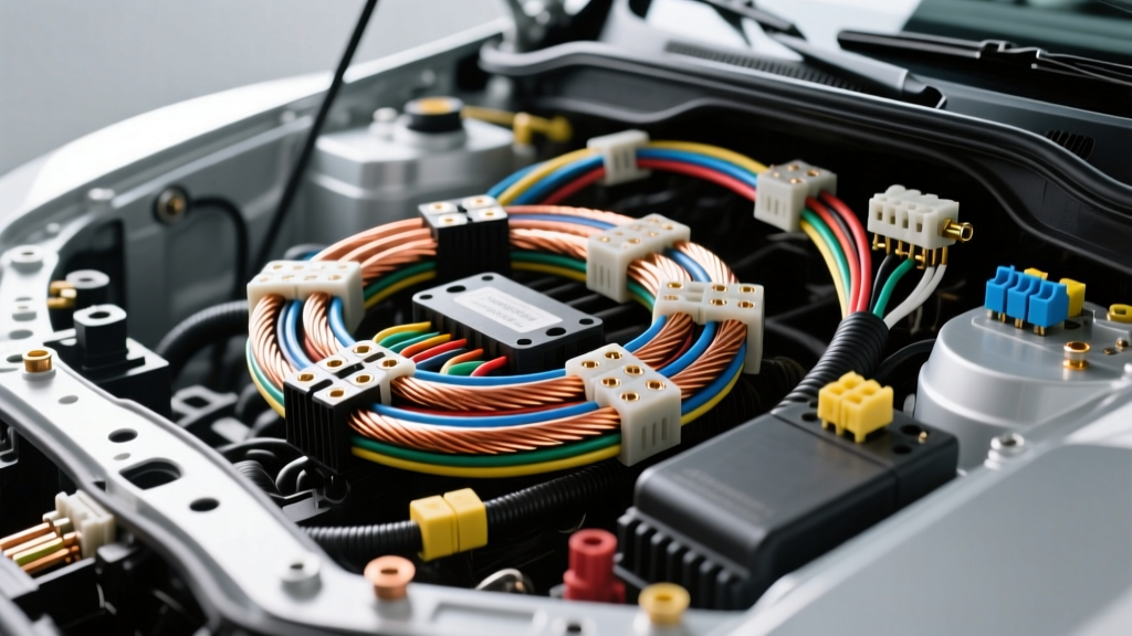
Advanced Engineering with 0000 Gauge Wire in High-Current Automotive Systems
When automotive electrical systems push beyond the limits of standard harnesses, 0000 gauge wire (commonly designated as 4/0 AWG) becomes the critical artery for power delivery. Whether you are engineering a custom 800V electric vehicle (EV) battery interconnect, wiring a 12,000-lb heavy-duty winch, or upgrading a dual-alternator system for expedition vehicles, understanding the exact metallurgical and electrical properties of 4/0 AWG is non-negotiable. Misjudging the ampacity, bend radius, or termination protocol at this scale doesn't just result in voltage drop; it leads to catastrophic thermal runaway and localized fires.
This advanced technical reference dissects the physical geometry, thermal ampacity ratings, voltage drop mathematics, and hydraulic termination requirements for 0000 gauge wire in demanding automotive and motorsport environments.
Physical Specifications and Conductor Geometry
The term '0000' represents four zeros, translating to the AWG designation 4/0. At this scale, the wire transitions from a standard conductor to a heavy-duty power cable. The physical construction of 0000 gauge wire is heavily dependent on its intended application—specifically, whether it is built to SAE J1128 (standard automotive battery cable) or SAE J1171 (marine and severe-duty ignition-protected cable).
To maintain flexibility in tight engine bays and battery enclosures, high-quality 4/0 AWG utilizes fine-stranding. A premium 0000 gauge welding or battery cable will feature upwards of 2,100 individual copper strands, allowing the cable to navigate complex chassis geometries without suffering from work-hardening and internal strand fracture.
| Parameter | Specification (SAE / ASTM B172) |
|---|---|
| AWG Designation | 4/0 (0000) |
| Cross-Sectional Area | 107.22 mm² |
| Conductor Diameter (Nominal) | 11.68 mm (0.460 inches) |
| Strand Count (Fine/Extra Fine) | 2107 x 30 AWG or 4204 x 36 AWG |
| DC Resistance @ 20°C (68°F) | 0.0490 Ω / 1000 ft (0.1608 Ω / km) |
| Weight (Copper Only) | 319 lbs / 1000 ft |
Source data aligns with the Copper Development Association standard bare copper wire tables.
Ampacity Ratings: Thermal Limits and Insulation Types
Ampacity is not a fixed number; it is a dynamic variable dictated by the insulation material's thermal rating and the cable's routing environment. The SAE J1128 standard outlines the requirements for high-temperature automotive primary wire, but 0000 gauge wire is typically classified under battery cable specifications (SAE J1128 Type SGT or equivalent XLPE insulated variants).
In a free-air environment (such as an exposed EV battery skid plate or an open-air rock crawler chassis), 0000 gauge wire can safely dissipate heat much more effectively than when bundled inside a sealed conduit or routed through a firewall grommet alongside other harnesses.
Continuous Ampacity vs. Peak Surge Ratings
Automotive applications rarely draw continuous, steady-state current. A starter motor or winch operates on a duty cycle. Therefore, we must differentiate between continuous chassis wiring ampacity and peak surge capacity.
| Insulation Type | Temp Rating | Continuous Ampacity (Free Air) | Continuous Ampacity (Bundled/Engine Bay) | Peak Surge (10-Second Duty Cycle) |
|---|---|---|---|---|
| PVC (Standard Battery) | 90°C | 260A | 195A | 600A |
| XLPE (Cross-Linked) | 125°C | 305A | 230A | 750A |
| EPDM (High-Temp Diesel) | 150°C | 335A | 255A | 850A |
| Silicone (Motorsport) | 200°C | 380A | 290A | 950A |
Note: When routing 0000 gauge wire through high-heat zones (e.g., near exhaust manifolds or turbocharger downpipes), you must apply a 20-30% derating factor unless utilizing specialized ceramic-fiberglass sleeving.
Voltage Drop Calculations for 12V and High-Voltage EV Architectures
Voltage drop is the silent killer of high-amperage automotive systems. In a 12V architecture, a drop of just 0.5V represents a significant loss of cranking power or winching torque. In 800V EV architectures (like those found in the Porsche Taycan or Hyundai Ioniq 5), voltage drop translates directly into I²R heating losses within the battery management system (BMS) interconnects.
The Voltage Drop Formula
To calculate the exact voltage drop for a 0000 gauge wire run, use the following formula:
VD = (2 × L × I × R) / 1000
- VD = Voltage Drop
- L = One-way length of the cable in feet
- I = Current in Amperes
- R = Resistance per 1000 ft of 4/0 AWG (0.0490 Ω at 20°C, but use 0.0550 Ω at 75°C operating temp)
Real-World Scenario: Heavy Duty Winching
Consider wiring a Warn Zeon 12-S winch (rated for 12,000 lbs) on an expedition truck. Under maximum stall load, the winch draws 430 Amps. The battery is in the rear cargo area, requiring a 25-foot positive run and a 25-foot negative run to the front bumper.
- L = 25 feet
- I = 430 Amps
- R = 0.0550 Ω (adjusted for thermal rise)
- VD = (2 × 25 × 430 × 0.0550) / 1000 = 1.18 Volts
A 1.18V drop on a 12V system means the winch motor receives only 10.82V under peak load. While 0000 gauge wire is sufficient to handle the thermal load without melting, the voltage drop will noticeably reduce winch line speed. For critical expedition rigs, upgrading to dual 4/0 runs or utilizing a secondary front-mounted auxiliary battery is the engineering solution to mitigate this drop.
Termination Protocols: Hydraulic Crimping and Lug Selection
The most common point of failure in 0000 gauge wire installations is not the wire itself, but the termination. Hand-crimpers are entirely inadequate for 107.2 mm² of copper. Achieving a gas-tight, cold-weld crimp requires specialized tooling and precise lug selection.
Tooling and Die Selection
For 4/0 AWG, you must use a minimum 8-ton hydraulic crimper (such as the Greenlee EK6412 or a comparable battery-actuated tool) or a heavy-duty manual ratcheting crimper with a 12-ton mechanical advantage. The choice of die geometry is critical:
- Hexagonal Dies: Provide a uniform, 6-sided crimp that is ideal for tight spaces and busbar connections. It minimizes the overall profile of the lug.
- Nest/Indent Dies: Create a deep indentation on one side and a flat nest on the other. This offers slightly higher pull-out strength and is preferred for heavy vibration environments like diesel engine bays.
Lug Material and Plating
Always use pure ETP (Electrolytic Tough Pitch) copper lugs, never aluminum. For automotive environments, the lugs must be electro-tinned to prevent galvanic corrosion and copper oxidation. When connecting to aluminum busbars (common in modern EV battery packs), you must apply a conductive anti-oxidant compound (such as NOALOX or Penetrox) to the mating surface to prevent the formation of aluminum oxide, which is highly resistive and causes thermal runaway at the joint.
Torque Specifications and Busbar Integration
Once the 0000 gauge wire is crimped, the mechanical connection to the busbar, contactor, or starter stud must be torqued to exact specifications. Under-torquing leads to micro-arcing and localized melting; over-torquing stretches the stud, reducing clamping force over time due to thermal cycling.
| Stud / Bolt Size | Standard Lug Thickness | Target Torque (Dry) | Target Torque (Lubricated/Oiled) |
|---|---|---|---|
| M8 (5/16') | 2.5 mm | 15 Nm (11 lb-ft) | 12 Nm (9 lb-ft) |
| M10 (3/8') | 3.2 mm | 28 Nm (21 lb-ft) | 22 Nm (16 lb-ft) |
| M12 (1/2') | 4.0 mm | 45 Nm (33 lb-ft) | 36 Nm (26.5 lb-ft) |
Always use Belleville (conical spring) washers or Nord-Lock washers under the nut when terminating 0000 gauge wire in high-vibration environments. Flat washers alone will not maintain clamping force as the copper lug undergoes thermal expansion and contraction.
Real-World Failure Modes and Troubleshooting
Even with perfect materials, field failures occur. As an automotive electrical diagnostic expert, here are the three most common failure modes associated with 0000 gauge wire installations:
- The 'Cold Crimp' Internal Fracture: If the hydraulic crimper was not fully cycled, or if the wrong die size was used, the outer strands compress while the inner core remains loose. Under high amperage, the loose inner strands arc internally, melting the insulation from the inside out. Diagnostic fix: Perform a millivolt drop test across the crimp barrel under load. A drop greater than 5mV indicates a failed crimp.
- Strand Clipping During Stripping: Using improper rotary cable strippers often nicks the outer strands of the 4/0 conductor. This reduces the effective cross-sectional area and creates stress risers where the wire will eventually snap under engine bay vibration. Diagnostic fix: Use a specialized parallel-blade wire stripper designed for fine-strand welding cable.
- Insulation Creep: Over time, the heavy weight of 0000 gauge wire pulling on a termination can cause the copper to 'creep' or stretch, pulling the lug barrel away from the insulation jacket. This exposes bare copper to moisture and road salt. Diagnostic fix: Always use dual-wall, adhesive-lined heat shrink (minimum 3/8 inch overlap onto the lug barrel and 1 inch onto the wire insulation) to create a waterproof, strain-relieved seal.
Conclusion
Integrating 0000 gauge wire into an automotive electrical system is a commitment to high-fidelity power transfer. By respecting the physical bend radius, calculating true operating voltage drop, and executing flawless hydraulic terminations, you ensure that high-amperage systems—from EV drivetrains to expedition winches—operate safely and efficiently under the most extreme conditions.
For further reading on severe-duty cable routing and marine-grade ignition protection standards, consult the Pacer Group technical resources and the latest SAE battery cable specifications.