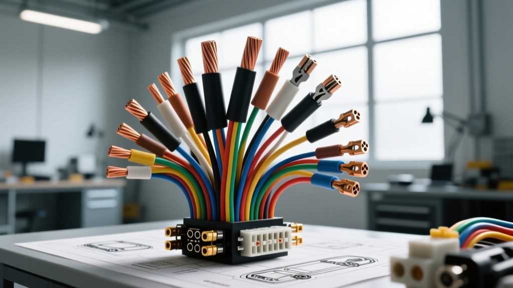
The "Highest Gauge Wire" Misconception: AWG Scale Explained
When automotive technicians and DIY enthusiasts search for the highest gauge wire, they are often navigating a common linguistic trap inherent to the American Wire Gauge (AWG) system. In the AWG standard, the physical diameter of the wire is inversely proportional to its gauge number. Therefore, the literal "highest gauge" wire in a standard automotive harness is actually the thinnest wire—typically ranging from 22 AWG to 30 AWG. These micro-diameter wires are critical for low-current, high-sensitivity signal transmission, such as oxygen sensor feedback, thermistor readings, and Controller Area Network (CAN) bus communication.
Conversely, many consumers mistakenly use the phrase "highest gauge" to describe the thickest wire (e.g., 1/0 AWG or 4 AWG) used for high-current applications like alternator upgrades, winch feeds, and starter circuits. To provide a complete, expert-level installation guide, this reference addresses both the literal highest-gauge (thin signal) wires and the colloquial highest-gauge (thick power) cables, ensuring your vehicle's electrical system is engineered to ISO 6722 Road Vehicle Cables standards.
Applications for True Highest Gauge Wires (22-30 AWG)
Modern Engine Control Modules (ECMs) and Transmission Control Modules (TCMs) rely on micro-gauge wiring to interpret data from precision sensors. Because these circuits carry less than 1 amp of current, voltage drop over short distances is negligible, but signal integrity and Electromagnetic Interference (EMI) resistance are paramount.
- Oxygen (O2) Sensors: Typically utilize 22 AWG to 20 AWG cross-linked polyethylene (XLPE) insulated wire for the signal return circuit. The narrowband signal fluctuates between 0.1V and 0.9V; any resistance introduced by a poor splice will cause false lean/rich fuel trims.
- CAN Bus Networks: Governed by SAE J1939 standards, high-speed CAN networks (CAN-C) operate at 500 kbps and require 24 AWG twisted-pair wiring to reject electromagnetic noise from the ignition system and alternator.
- Thermistors and MAF Sensors: Often use 24 AWG to 26 AWG wire to transmit low-voltage analog signals back to the ECM.
SAE J1939 CAN Bus Wiring Specifications
When installing or repairing the highest gauge signal wires on a CAN bus network, strict adherence to color codes and topology is required:
- CAN High (CAN-H): Typically White or Yellow (varies by OEM, e.g., GM uses Dark Green, Ford uses White/Light Blue).
- CAN Low (CAN-L): Typically Green or Blue (GM uses Dark Blue, Ford uses White/Light Green).
- Twist Rate: Wires must be twisted at a rate of 1 twist per inch (approx. 40 twists per meter) to maintain common-mode noise rejection.
- Termination: The bus requires exactly two 120-ohm terminating resistors at the physical ends of the network. Splicing into the middle of a CAN bus without maintaining the twisted pair architecture will cause reflection errors and U-codes (e.g., U0100 Lost Communication with ECM).
Step-by-Step Installation Guide for High-Gauge Signal Wires
Working with 24-30 AWG wire requires specialized tools and techniques. Standard automotive crimpers will destroy micro-terminals, and standard wire strippers will nick the fragile copper strands, leading to fatigue failures under engine vibration.
Step 1: Precision Stripping
Do not use standard pliers or heavy-duty strippers. Use a precision micro-stripper calibrated for 24-30 AWG, such as the Knipex Micro Stripax or an automated thermal wire stripper. Thermal strippers use a heated blade to melt through the insulation without mechanically touching the copper strands, guaranteeing zero nicking. Strip exactly 3mm to 5mm of insulation, depending on the terminal barrel depth.
Step 2: Micro-Crimping Terminals
For modern sealed connectors like TE Connectivity AMPSEAL or Molex MX150 systems, you must use the OEM-specified micro-terminal.
- Insert the 24 AWG wire into the terminal's wire grip barrel.
- Use a ratcheting micro-crimper (e.g., TE Connectivity CERTI-CRIMP tooling) to ensure the crimp is fully seated. A ratcheting tool prevents the release of the crimp before the exact compression force is achieved.
- Verify the crimp by performing a pull-test. A properly crimped 24 AWG terminal should withstand a minimum pull force of 15 lbs before the wire yields.
Step 3: Environmental Sealing and Heat Shrinking
If you are splicing a highest gauge wire outside of a sealed connector cavity, you must use dual-wall, adhesive-lined polyolefin heat shrink.
- Slide the heat shrink over the wire before making the connection.
- Use a Western Union splice (twisting the strands together) followed by a rosin-core solder joint. Avoid acid-core flux, which will corrode the micro-strands.
- Center the adhesive-lined heat shrink over the solder joint and apply heat evenly with a micro-torch or heat gun (set to 250°C / 480°F).
- Watch for the adhesive to melt and squeeze out of both ends, indicating a watertight, vibration-proof seal.
Addressing the Layman Intent: Installing Low-Gauge (Thick) Power Wires
If your search for "highest gauge wire" was intended to find the thickest wire for high-amperage accessories (colloquially misusing the AWG scale), you are looking at 1/0 AWG, 2/0 AWG, or 4 AWG cables. These are used for alternator-to-battery runs, starter feeds, and high-power audio amplifiers.
Installation Rules for Thick Power Cables:
- Lugging: Use closed-end copper ring terminals. Crimp using a hex-indent hydraulic crimper to ensure maximum surface contact and prevent hot spots.
- Torque Specs: Battery terminal studs and alternator B+ posts must be torqued to manufacturer specifications (typically 10-15 Nm for standard M8 studs). Under-torquing causes arcing and alternator diode failure.
- Routing: Keep 1/0 AWG power cables at least 18 inches away from sensitive high-gauge signal wires and RCA cables to prevent inductive coupling and alternator whine.
- Protection: Always wrap thick power cables in split-loom tubing or Techflex braided sleeving where they pass through the firewall or near exhaust manifolds. Use a heavy-duty rubber grommet and silicone sealant at all firewall penetration points.
Technical Reference Chart: AWG Size, Resistance, and Ampacity
The following matrix outlines the physical and electrical properties of both literal high-gauge (thin) and colloquial high-gauge (thick) automotive wires. Ampacity ratings are based on SAE J1128 standards for single-conductor cables in engine compartment environments (assuming 105°C XLPE insulation and bundled routing conditions).
| AWG Size | Diameter (mm) | Ohms per 1,000 ft (Copper) | Max Ampacity (Chassis/Bundled) | Primary Automotive Application |
|---|---|---|---|---|
| 30 AWG | 0.254 | 103.20 | 0.5A | ECU internal jumpers, micro-sensors |
| 24 AWG | 0.511 | 25.67 | 2.0A | CAN Bus networks, low-current signal returns |
| 20 AWG | 0.812 | 10.15 | 5.0A | O2 sensor signals, injector pulse wiring |
| 16 AWG | 1.290 | 4.01 | 10.0A | Headlights, fuel pumps, blower motors |
| 10 AWG | 2.588 | 0.99 | 30.0A | Ignition feeds, ABS module power, horn relays |
| 4 AWG | 5.189 | 0.24 | 100.0A | Audio amplifiers, winch feeds, starter relays |
| 1/0 AWG | 8.251 | 0.09 | 150.0A | Alternator upgrades, main battery-to-starter runs |
Troubleshooting High-Gauge Signal Wire Failures
When working with 22-30 AWG signal wires, failures rarely present as blown fuses. Instead, they manifest as data corruption, erratic sensor readings, or module communication dropouts. Use the following diagnostic decision tree to isolate faults in highest gauge wiring harnesses.
Symptom: Intermittent CAN Bus Communication Codes (U0100, U0140)
- Potential Cause 1: Untwisted wire repair in the CAN-H / CAN-L circuit.
- Fix: Cut out the untwisted splice. Re-splice using 24 AWG wire and restore the 1-twist-per-inch geometry. Verify network termination resistance reads exactly 60 ohms across the OBD2 pins 6 and 14.
- Potential Cause 2: Micro-corrosion at the ECM connector cavity due to capillary wicking.
- Fix: If a previous technician soldered a wire without adhesive-lined heat shrink, moisture may have wicked under the insulation into the ECM seal. Depin the connector, cut back the wire past the corrosion line, and install a new TE Connectivity terminal with proper cavity plugs.
Symptom: Erratic Short-Term Fuel Trims / O2 Sensor Lazy Codes (P0133)
- Potential Cause 1: High resistance in the 22 AWG signal return wire.
- Fix: Perform a voltage drop test on the signal return circuit with the key on, engine off (KOEO). Backprobe the O2 sensor connector and the ECM pin simultaneously. A voltage drop greater than 50mV on a low-current signal wire indicates a failing crimp or internal strand breakage.
- Potential Cause 2: EMI interference from aftermarket ignition coils.
- Fix: Ensure the O2 sensor signal wire is not routed parallel to spark plug wires or aftermarket coil packs. Reroute the harness and secure it with high-temperature P-clips.
Symptom: MAF Sensor Circuit Low Input (P0102)
- Potential Cause: Pin drag or terminal spread in the 24 AWG MAF connector.
- Fix: Inspect the female terminal cavity. If the micro-terminal has lost its spring tension (often caused by using the wrong male probe during testing), the entire pigtail must be replaced. Never use standard paperclips or oversized test leads to backprobe highest gauge micro-connectors.
By understanding the inverse nature of the AWG scale and applying the correct micro-crimping, sealing, and routing techniques, you ensure that both the literal highest gauge signal wires and the heaviest power cables in your vehicle operate flawlessly under the harshest automotive environments.