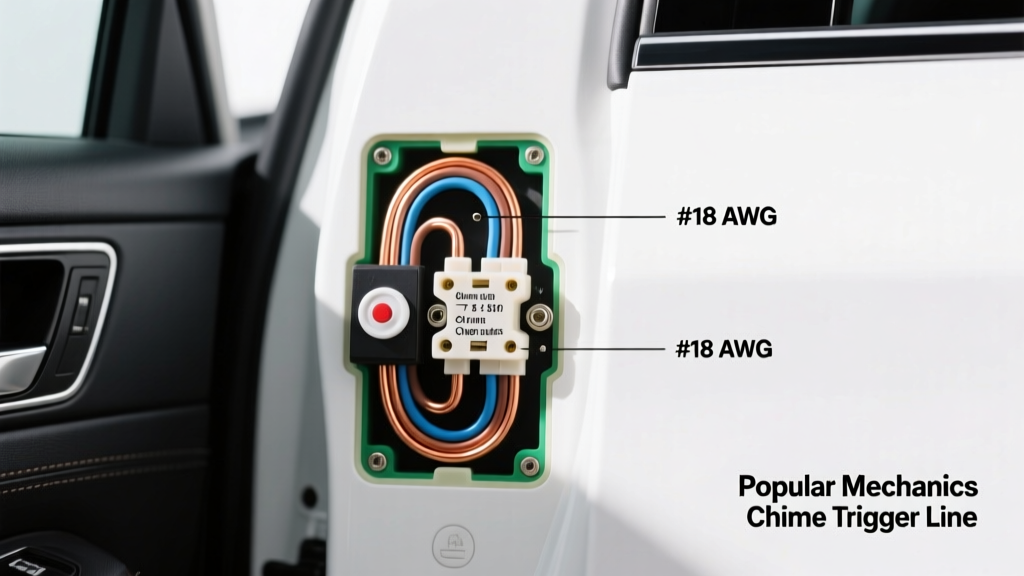
Understanding the "Door Bell" Circuit in Automotive Applications
When enthusiasts and technicians search for door bell wire gauge, they are often crossing over from residential electrical terminology into automotive low-current signal circuits. In a house, a doorbell circuit typically relies on 18 AWG copper wire carrying 16-24V AC. In an automotive upgrade or modification project, the equivalent "door bell" circuit refers to the door trigger, courtesy light, and chime module wiring. These circuits operate on a 12V DC nominal system (13.5V–14.4V while charging) and dictate the behavior of dome lights, aftermarket security alarms, and OEM door-ajar chimes.
Whether you are retrofitting a classic muscle car with modern door-ajar warning chimes, integrating an aftermarket alarm system's door trigger, or upgrading heavy-duty courtesy lighting, selecting the correct wire gauge is critical. Using wire that is too thin leads to voltage drop and module malfunction; using wire that is too thick makes routing through the flexible rubber door jam boots nearly impossible and increases the risk of copper fatigue and wire breakage.
Standard Automotive Door Trigger Wire Gauge Specifications
Factory door trigger wires are typically designed to carry minimal current—often just a few milliamps to signal a Body Control Module (BCM) or a simple ground-switched path for a relay. However, modification projects often add new loads. The table below outlines the correct door bell wire gauge selections based on the specific upgrade application.
| AWG Size | Max Current (Chassis) | Primary Upgrade Application | Recommended Insulation Type |
|---|---|---|---|
| 20 AWG | 5 Amps | OEM BCM signal taps, alarm door trigger inputs | Cross-linked PE (GXL/TXL) |
| 18 AWG | 9 Amps | Standard LED courtesy lights, basic door chime modules | PVC or GXL |
| 16 AWG | 13 Amps | High-output LED puddle lights, multiplexed relay triggers | GXL / Marine-grade tinned |
| 14 AWG | 17 Amps | Power feed for door-mounted audio speakers or heavy actuators | SGT / GXL |
For standard aftermarket alarm door trigger inputs (which are high-impedance sensing circuits), 20 AWG to 18 AWG GXL wire is the industry standard. GXL (General Cross-Linked) insulation is thinner than standard PVC, allowing you to bundle multiple signal wires together when routing through the tight confines of an A-pillar or door jamb boot.
Upgrade Project: Wiring Aftermarket Alarms and Door Chimes
When installing an aftermarket alarm or a standalone door chime module (like those used in vintage hot rod restomods), you must interface with the vehicle's door jamb switches. The wiring strategy depends entirely on the vehicle's factory switching logic.
1. Identifying Your Door Trigger Type
- Negative Trigger (Ground Switched): Common in older domestic and many Asian vehicles. The door switch completes the path to ground when the door opens. The factory wire will read 12V when the door is closed, and 0V when open. Alarm Connection: Tap this wire and connect it to the alarm's Green (Negative Trigger) input wire.
- Positive Trigger (12V Switched): Common in many European vehicles and some Fords. The door switch provides +12V to the dome light circuit when opened. The wire reads 0V closed, and +12V open. Alarm Connection: Tap this wire and connect it to the alarm's Violet (Positive Trigger) input wire.
- Multiplexed / CAN-Bus Data: Found in modern vehicles (roughly 2010+). The door switch sends a digital data packet to the BCM rather than a simple 12V/0V analog signal. Upgrade Solution: Do not tap the switch directly. Use a CAN-Bus interface module (like an iDatalink Maestro or Fortin EVO) to translate the data into a standard 18 AWG analog negative trigger output for your chime or alarm.
2. Splicing and Tapping the Trigger Wire
When tapping into the factory door trigger wire to feed a new chime module or alarm brain, avoid "scotch locks" or vampire taps. These pierce the insulation, allowing moisture to wick into the copper strands via capillary action, leading to green corrosion and eventual open-circuit failures. Instead, use the T-Tap and solder method, or strip back the factory loom, perform a parallel solder splice using 20 AWG stranded wire, and seal the connection with adhesive-lined dual-wall heat shrink.
Sizing for High-Draw Modifications: Puddle Lights and LED Arrays
A common modification project involves replacing dim, factory incandescent courtesy bulbs with high-lumen LED puddle light arrays or illuminated door sill plates. While LEDs are efficient, large arrays or fiber-optic door sill kits can draw 3 to 6 amps continuously.
The factory "door bell" or courtesy wire (often 20 AWG or even 22 AWG in modern thin-wire harnesses) is not rated to carry this continuous load without experiencing severe voltage drop or melting the insulation.
The Relay Bypass Solution
If your new door lighting upgrade draws more than 5 amps, you must upgrade the wire gauge and isolate the factory circuit using a standard Bosch-style 12V 30A relay.
- Pin 86 (Coil +): Connect to a switched 12V ignition source using 16 AWG wire.
- Pin 85 (Coil -): Connect to the factory door trigger wire (using 18 AWG). The factory switch now only carries the tiny milliamp load required to energize the relay coil.
- Pin 30 (Common): Connect directly to the battery positive terminal via an inline fuse (rated for your LED array) using 14 AWG or 12 AWG primary wire.
- Pin 87 (Normally Open): Run 16 AWG wire through the door boot directly to your high-draw LED puddle lights or sill plates.
This setup ensures your heavy lighting modification receives full system voltage without overloading the delicate factory BCM or thin-gauge door trigger wiring.
Best Practices for Routing Through the Door Boot
The most hostile environment for any automotive wire is the flexible rubber boot connecting the A-pillar to the front door hinge area. Every time the door opens and closes, the wires inside are subjected to extreme bending, tension, and compression. Over time, standard solid-core "door bell wire" (often mistakenly purchased from hardware stores for automotive projects) will snap immediately due to metal fatigue.
Material and Routing Rules
- Never Use Solid Core: Always use high-strand-count, flexible stranded copper wire. Marine-grade tinned copper (such as Ancor brand) offers the highest flexibility and corrosion resistance.
- Wrap in Loom or Tesa Tape: Bundle your new 18 AWG or 16 AWG wires and wrap them in Tesa 51036 PET cloth tape. This prevents the wires from rubbing against each other and creating squeaks or insulation wear inside the rubber boot.
- Service Loop: Leave a slight "service loop" (extra slack) on both the A-pillar and door side of the boot to prevent the wires from pulling taut when the door is fully opened to its maximum hinge angle.
Authoritative References & Standards
When planning your modification project, always adhere to established automotive electrical standards to ensure safety and longevity. For wire insulation types and temperature ratings, refer to the SAE J1128 Standard for Low Tension Primary Cable, which dictates the requirements for GXL, TXL, and SGT wire classifications used in vehicle chassis wiring. For proper circuit protection and relay integration guidelines, the MEI (Mobile Electronics Industry) association provides excellent best-practice documentation for aftermarket alarm and accessory installations, ensuring your door trigger and chime upgrades operate flawlessly for years to come.