Introduction to 23 AWG in Automotive Signal Circuits
When building or repairing modern automotive wiring harnesses, especially in motorsport and performance data-logging applications, selecting the correct wire gauge is critical for signal integrity. While 18 AWG and 16 AWG dominate power and ground circuits, 23 gauge wire occupies a highly specialized niche: low-current, high-impedance analog sensor signals. Unlike power circuits that suffer from voltage drop over long runs, 0-5V analog sensor circuits (such as MAP, EGT, and thermocouple inputs) draw less than 10 milliamps. In these applications, the primary concerns are weight reduction, harness flexibility, and physical routing rather than ampacity.
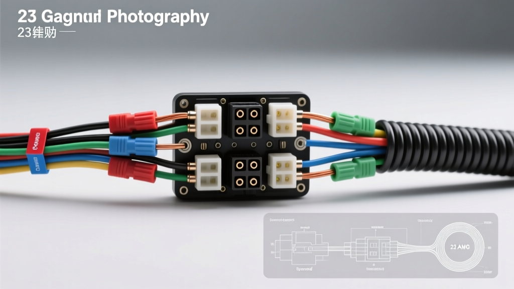
This complete wiring diagram walkthrough will trace a high-performance sensor signal harness from the ECU connector to the sensor pigtail, detailing exactly how and why 23 AWG wire is deployed, terminated, and shielded in professional motorsport environments.
23 Gauge Wire Technical Specifications
Before tracing the diagram, it is essential to understand the physical and electrical properties of 23 AWG wire. In automotive applications, this wire is typically insulated with TXL (cross-linked polyethylene) for standard engine bays, or Tefzel (ETFE) for MIL-SPEC motorsport harnesses due to its superior heat and chemical resistance.
| Specification | 23 AWG Value | Notes / Application Context |
|---|---|---|
| Nominal Diameter | 0.573 mm (0.0226 in) | Allows for high-density ECU connector pinning |
| Cross-Sectional Area | 0.258 mm² | Often substituted with 0.22mm² (24 AWG) in strict metric harnesses |
| Stranding (High-Flex) | 19/34 AWG | Essential for harnesses subjected to engine vibration |
| Resistance (Copper) | 21.7 Ω / 1000 ft | Negligible voltage drop at <10mA sensor signal loads |
| Max Ampacity (Chassis) | 1.4 Amps | Strictly for signals; never use for 12V power or ground |
| Weight | 1.8 lbs / 1000 ft | Significant weight savings over 18 AWG in 60+ wire harnesses |
For comprehensive standards on low-tension primary cable insulation and temperature ratings, refer to the SAE J1128 specification, which governs thin-wall automotive wire insulation requirements.
Wiring Diagram Walkthrough: Performance Sensor Harness
For this walkthrough, we are examining a Manifold Absolute Pressure (MAP) sensor and Exhaust Gas Temperature (EGT) analog input harness connected to a standalone Engine Control Unit (ECU). We will use a TE Connectivity Deutsch DTM 12-pin connector at the ECU firewall bulkhead, transitioning to a Bosch EV1 3-pin connector at the sensor.
Step 1: ECU Connector Pinout & Initialization
The signal originates inside the ECU and exits through the main bulkhead connector. High-density ECU connectors (like the Molex MX150 or TE AMPSEAL) easily accommodate 23 gauge wire due to the small terminal footprint.
- ECU Pin A12 (Sensor Ground): 23 AWG Black (TXL). This is a dedicated, isolated analog ground. It must not be shared with injector or ignition grounds to prevent induced noise.
- ECU Pin A13 (MAP Signal): 23 AWG White with Red Tracer. This carries the 0-5V analog voltage back to the ECU's ADC (Analog-to-Digital Converter).
- ECU Pin A14 (5V Reference): 20 AWG Red. Note: While the signal and ground can be 23 AWG, the 5V reference is often stepped up to 20 AWG or 18 AWG to ensure absolute voltage stability if multiple sensors share the same 5V rail.
Step 2: Sensor Pigtail Routing & Color Codes
Tracing the harness through the engine bay, the 23 AWG wires are bundled into a convoluted loom or braided sleeving. As we approach the MAP sensor (mounted on the intake plenum), the harness breaks out into a flexible pigtail.
At the Bosch EV1 3-Pin Sensor Connector, the pinout matches as follows:
- Pin 1 (Reference In): Red 20 AWG
- Pin 2 (Signal Out): White/Red 23 AWG
- Pin 3 (Sensor Ground): Black 23 AWG
Because 23 gauge wire is exceptionally thin, it is highly susceptible to physical abrasion. Professional harness builders will apply Raychem DR-25 heat shrink tubing over the breakout point where the 23 AWG wires separate from the main harness bundle to prevent chafing against the intake manifold.
Step 3: Shielding and Grounding the Drain Wire
Analog 0-5V signals are highly vulnerable to Electromagnetic Interference (EMI) generated by ignition coils and alternators. To protect the 23 AWG signal wire, it is routed inside a shielded twisted pair (STP) configuration.
The shield consists of a braided copper sleeve with a bare 24 AWG drain wire running parallel to the 23 AWG signal and ground wires. Critical Rule: The drain wire must be grounded at the ECU end only (Pin A15: Chassis Ground). Grounding the shield at both the ECU and the sensor creates a ground loop, which will introduce severe 60Hz+ alternator whine into the 23 AWG signal line, causing erratic ECU fueling calculations.
Crimping and Terminal Selection for 23 AWG
Terminating 23 gauge wire requires precision. Standard automotive open-barrel crimpers often crush or cut the thin strands of 23 AWG if the die is not perfectly calibrated. When pinning into a Deutsch DTM connector, you must use Size 20 contacts, which are rated for 20-24 AWG wire.
The crimp must be verified under magnification. A proper crimp on 23 AWG wire will show the wire strands slightly flaring out at the front of the conductor crimp (the 'bellmouth'), ensuring the wire is fully seated without being sheared by the crimp wings. The insulation crimp must grip the TXL/Tefzel jacket tightly to provide strain relief; otherwise, engine vibration will fatigue the 0.573mm copper core, leading to an intermittent open circuit.
Signal Integrity: EMI, RFI, and Twisted Pair Requirements
Why use 23 AWG instead of standard 18 AWG for signals? Beyond weight savings, thinner wires allow for tighter twisting. A twisted pair of 23 AWG wires can achieve 6 to 8 twists per inch, compared to just 2 or 3 twists per inch for 18 AWG. This higher twist rate drastically improves Common Mode Rejection Ratio (CMRR), effectively canceling out RFI from high-output ignition systems like CDI or COP (Coil-on-Plug) setups.
When routing the 23 AWG sensor harness, maintain a minimum clearance of 4 inches (100mm) from any high-current wiring (fuel pump feeds, starter cables) and at least 2 inches from ignition coil primary wiring. If crossing high-current wires is unavoidable, the 23 AWG signal bundle must cross at a strict 90-degree angle to minimize inductive coupling.
Troubleshooting Decision Tree: 23 AWG Signal Loss
Because 23 gauge wire has a higher resistance per foot (21.7 Ω/1000ft) than thicker gauges, diagnosing faults requires a different approach. Voltage drop testing is largely ineffective here due to the micro-ampere current draw. Use this decision tree when diagnosing erratic sensor readings:
- Symptom: Sensor reads 5.0V constantly (Open Circuit).
- Cause: The 23 AWG signal wire has fractured inside the insulation near the crimp terminal due to vibration fatigue.
- Fix: Perform a continuity test from the sensor pigtail to the ECU bulkhead. Re-crimp using a fresh DTM Size 20 pin and apply strain-relief heat shrink.
- Symptom: Sensor reads 0.0V or fluctuates wildly with engine RPM.
- Cause: EMI induction or a short to ground. The thin insulation of 23 AWG Tefzel wire may have melted against the exhaust manifold, shorting the signal to the chassis.
- Fix: Inspect the physical routing. Reroute the harness, replace the damaged 23 AWG section, and upgrade the shielding braid.
- Symptom: Sensor reads 1.5V offset from actual pressure.
- Cause: Ground loop on the shield drain wire, or shared 23 AWG ground wire carrying return current from another high-draw sensor.
- Fix: Verify the 23 AWG Black ground wire is dedicated solely to the MAP sensor and traces back to the ECU's dedicated analog ground plane.
For further reading on ECU pinouts, sensor impedance matching, and harness fabrication standards, consult the Haltech Elite Wiring Manuals, which provide excellent visual references for analog signal wire routing and termination best practices in motorsport environments.
Conclusion
While 23 gauge wire is rarely seen in standard consumer vehicle power distribution, it is the backbone of high-end motorsport sensor networks. By understanding its physical limitations, leveraging its flexibility for tight twisted-pair routing, and utilizing proper micro-crimping techniques, you can build a bulletproof analog signal harness that delivers noise-free data to your ECU, ensuring optimal engine tuning and reliability.