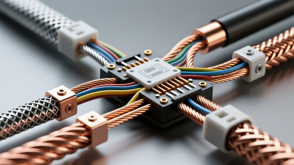
The Role of Wire Mesh in Modern Vehicle Architecture
In the context of automotive electrical systems, the term wire mesh rarely refers to rigid fencing. Instead, it denotes braided shielding sleeves, woven EMI/RFI protection, and flexible flat grounding straps. As modern vehicles integrate advanced driver-assistance systems (ADAS), high-voltage electric vehicle (EV) powertrains, and high-speed CAN FD networks, protecting sensitive signals from electromagnetic interference (EMI) is paramount. Selecting the correct gauge of wire mesh for these applications is a critical engineering decision that impacts signal integrity, weight, and long-term harness reliability.
Wire mesh shielding operates on the principle of the Faraday cage. When an electromagnetic field strikes the conductive mesh, the electrical currents are distributed along the exterior of the weave, canceling the field's effect on the interior conductors. However, the effectiveness of this shield is directly tied to the physical dimensions of the weave, specifically the gauge of the individual wire strands used to create the mesh, the picks per inch (PPI), and the resulting optical coverage.
Decoding the Gauge of Wire Mesh for EMI Attenuation
The gauge of wire mesh dictates both the mechanical durability and the high-frequency attenuation capabilities of the shield. In automotive harness manufacturing, shielding braids are typically constructed from tinned copper, bare copper, or aluminum alloys. The individual strands in these braids usually range from 32 AWG to 36 AWG for standard low-voltage signal cables, and up to 24 AWG for heavy-duty high-voltage EV shielding.
A finer gauge of wire mesh (e.g., 36 AWG strands) allows for a tighter weave with higher picks per inch. This high-density weave provides superior optical coverage (often exceeding 95%), which is essential for blocking high-frequency RF interference generated by ignition coils, alternators, and radar sensors. Conversely, a thicker gauge of wire mesh (e.g., 24 AWG to 28 AWG strands) provides lower optical coverage but offers significantly lower DC resistance and higher mechanical strength, making it ideal for low-frequency magnetic shielding and heavy-duty grounding applications.
Technical Specification Chart: Wire Mesh Gauge vs. Application
The following reference table outlines standard automotive wire mesh specifications, correlating the strand gauge with typical harness applications and SAE standards.
| Mesh Strand AWG | Picks Per Inch (PPI) | Optical Coverage | Primary Automotive Application | SAE / ISO Reference |
|---|---|---|---|---|
| 36 AWG (Tinned Cu) | 80 - 110 PPI | 96% - 98% | CAN FD, LIN Bus, Radar/ADAS Sensor Shielding | SAE J1939, ISO 11898-2 |
| 32 AWG (Tinned Cu) | 50 - 70 PPI | 90% - 95% | Standard Sensor Wiring, ABS/ESC Harnesses | SAE J1128, SAE J2223 |
| 28 AWG (Al/Cu) | 40 - 60 PPI | 85% - 90% | Infotainment, GPS Antennas, Coaxial Shielding | SAE J1128 |
| 24 AWG (Flat Braid) | N/A (Flat Weave) | N/A | Engine-to-Chassis Grounding, Battery Negative | SAE J1292, QS 9000 |
| 22-24 AWG (EV HV) | 30 - 50 PPI | 80% - 90% | High-Voltage EV Drive Cables (Orange Jacket) | ISO 6722-2, LV 112-2 |
High-Voltage EV Harnesses vs. Low-Voltage CAN Bus
The requirements for the gauge of wire mesh diverge sharply depending on whether the harness is carrying high-voltage propulsion current or low-voltage data signals.
CAN Bus Shielding and Pin Configurations
For heavy-duty vehicle networks governed by SAE J1939, the CAN bus relies on a twisted pair of wires (typically CAN-High in white/green and CAN-Low in white/brown or yellow). To prevent common-mode noise from corrupting the differential signal, a 36 AWG tinned copper wire mesh braid is applied over the twisted pair. This fine gauge of wire mesh ensures maximum coverage without adding excessive stiffness to the harness. In a standard 9-pin Deutsch DT diagnostic connector, Pin A is CAN-H, Pin B is CAN-L, and Pin C or the connector backshell is dedicated to the shield drain wire, which must be in continuous contact with the interior of the wire mesh.
EV High-Voltage Shielding Requirements
In electric vehicles, the high-voltage (HV) cables carrying 400V to 800V from the inverter to the drive motors generate massive electromagnetic fields. The shielding here serves a dual purpose: protecting nearby low-voltage logic circuits from the HV noise, and protecting passengers from EMF exposure. Because HV cables are thick (ranging from 2 AWG to 4/0 AWG), the shielding mesh must be highly flexible to allow for tight bend radii in the chassis. Manufacturers often use an aluminum alloy wire mesh (typically 24 AWG to 28 AWG strands) for EV applications. Aluminum reduces harness weight by up to 40% compared to copper, though it requires specialized ferrule crimping to prevent galvanic corrosion when terminating the shield to the inverter housing.
Flexible Grounding Straps: Mesh as a Conductor
When wire mesh is used as a grounding strap rather than a shield, the gauge of wire mesh refers to the cumulative AWG of the flat braided strap. Engine blocks and transmissions are isolated from the chassis by rubber motor mounts, necessitating heavy-duty grounding straps to carry starter motor return currents (often exceeding 400 amps) and alternator ground currents. These straps are woven from thousands of 34 AWG copper strands, bundled into a flat mesh configuration. The flat mesh geometry provides extreme flexibility to absorb engine torque roll and vibration without suffering from metal fatigue, a common failure point in solid wire ground cables. For a standard V8 engine-to-chassis ground, a flat wire mesh strap equivalent to 2 AWG or 1/0 AWG is required, typically terminated with seamless copper ring terminals and secured with M8 or M10 flange bolts torqued to 25-30 Nm to ensure a gas-tight, low-resistance connection.
Real-World Failure Modes and Diagnostics
Improper selection or degradation of the wire mesh shield leads to specific, diagnosable electrical faults:
- Galvanic Corrosion in EV Harnesses: If a copper mesh braid is used over an aluminum HV cable jacket without proper separation, moisture ingress creates a galvanic cell. The resulting corrosion turns the mesh into a high-resistance insulator, leading to EMF leakage and potential inverter fault codes.
- CAN Bus U-Codes (e.g., U0100): If the fine 36 AWG mesh shield is compromised by chafing against a sharp chassis bracket, the optical coverage drops. High-frequency alternator whine infiltrates the twisted pair, causing the CAN transceivers to detect excessive bit errors and drop nodes off the network.
- Ground Strap Fatigue: Using a solid wire instead of a flat wire mesh braid for engine grounding will result in the wire snapping at the crimp barrel within 10,000 miles due to the harmonic vibration of the powertrain.
Terminating the Shield: 360-Degree vs. Pigtail
The effectiveness of any gauge of wire mesh is nullified if terminated poorly. The industry standard for high-speed data and HV shielding is the 360-degree crimp ring or backshell termination, which wraps the mesh entirely around the connector body, maintaining the Faraday cage uninterrupted. The outdated method of twisting the mesh into a single 'pigtail' drain wire creates an inductive choke at high frequencies, effectively turning the shield into an antenna that broadcasts interference into the cabin. Always utilize connectors with integrated EMI backshells (such as the TE Automotive DEUTSCH or Amphenol AT series) to clamp the mesh uniformly.
For comprehensive guidelines on primary cable insulation and shielding integration, refer to the baseline testing parameters outlined in SAE J1128. Understanding the physics of weave density and strand gauge ensures that your automotive electrical designs remain robust against the increasingly hostile electromagnetic environment of modern vehicles.