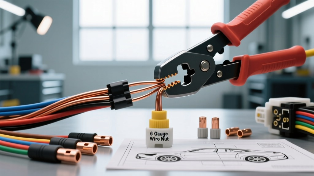
The Truth About Using Wire Nuts for 6 Gauge Wire
When DIY mechanics and novice installers search for wire nuts for 6 gauge wire, they are typically attempting to splice heavy-duty, high-amperage circuits. Common applications include alternator upgrades for LS-swapped vehicles, winch power feeds on heavy-duty trucks, or main power distribution for high-output car audio systems. However, using standard twist-on wire connectors (commonly known by the brand name Wire-Nut) on 6 AWG cable is a critical safety hazard in automotive environments.
Standard twist-on connectors are engineered for solid-core or lightly stranded copper wire used in residential AC wiring (NFPA 70). They rely on a tapered steel spring to bite into the wire and maintain tension. Automotive environments subject wiring to extreme thermal cycling, high-frequency vibration, and corrosive elements. A twist-on connector cannot maintain the necessary clamp force on heavily stranded 6 AWG SAE J1128 battery cable, leading to arcing, localized melting, and catastrophic electrical fires.
Ampacity and Mechanical Limits of 6 AWG Automotive Cable
To understand why proper termination is mandatory, we must examine the physical and electrical properties of 6 AWG wire. According to the SAE J1128 Standard for low-tension primary and battery cable, 6 AWG wire is designed to carry substantial continuous current, making secure, low-resistance connections non-negotiable.
| Specification | 6 AWG SAE J1128 (Battery Cable) | 6 AWG THHN (Chassis/House) |
|---|---|---|
| Stranding Configuration | 259 x 30 AWG (Highly Flexible) | 19 x 29 AWG (Semi-Rigid) |
| Conductor Diameter (Nominal) | 0.184 inches (4.67 mm) | 0.162 inches (4.11 mm) |
| Overall Insulation OD | 0.290 inches (7.37 mm) | 0.240 inches (6.10 mm) |
| Max Ampacity (Chassis/Free Air) | 60A - 120A (Depending on length/duty) | 55A - 75A |
| Resistance @ 20°C | 0.410 Ω / 1000 ft | 0.395 Ω / 1000 ft |
Why Twist-On Connectors Fail in Automotive 6 AWG Circuits
If you attempt to force a large twist-on connector onto 6 AWG wire, you will encounter three primary failure modes:
- Vibration Loosening (SAE J2149): The 259 fine strands of automotive 6 AWG wire compress and 'creep' over time under the steel spring of a wire nut. Engine bay vibration accelerates this cold-flow, causing the connection to loosen, increase resistance, and generate heat.
- Thermal Expansion Mismatch: Under-hood temperatures can exceed 125°C (257°F) near exhaust headers. The copper wire and the steel spring inside the connector expand and contract at different rates, breaking the mechanical bite of the connector.
- Moisture and Corrosion Ingress: Twist-on connectors offer zero environmental sealing. Road salt, humidity, and engine bay fluids will wick into the exposed copper strands via capillary action, leading to copper oxide buildup (green corrosion), which acts as an electrical insulator and causes severe voltage drop.
The Correct Alternatives to Wire Nuts for 6 AWG
Instead of searching for non-existent automotive-rated twist-on nuts, professional auto electricians rely on mechanical crimping combined with environmental sealing. Below are the industry-standard alternatives for splicing and terminating 6 AWG wire.
1. Adhesive-Lined Heat Shrink Butt Splices
For inline splices (e.g., extending a winch power cable or repairing a damaged alternator feed), adhesive-lined heat shrink butt splices are the gold standard. These terminals feature a copper barrel for the mechanical crimp and a dual-wall polyolefin outer jacket. The inner wall is lined with a thermoplastic hot-melt adhesive that melts during heating, flowing into the wire strands to create a completely waterproof, gas-tight seal. TE Connectivity and Molex manufacture heavy-duty variants specifically rated for 6 AWG to 4 AWG wire.
2. Closed-End Crimp Caps (The 'Automotive Wire Nut')
If your goal is to cap the end of a 6 AWG wire or create a pigtail splice (e.g., tapping a heavy-gauge battery feed to power a relay coil), closed-end crimp caps are the correct tool. Unlike twist-on nuts, these are copper or aluminum barrels closed at one end. You insert the wires and use a heavy-duty crimper to deform the barrel, creating a permanent, cold-welded mechanical bond.
3. High-Amp Terminal Blocks and Busbars
For distribution (e.g., connecting multiple 6 AWG accessory feeds to a main battery line), do not twist wires together. Use a solid copper busbar with M8 or M10 stainless steel studs, secured with ring terminals and torqued to the manufacturer's specification (typically 10-15 Nm for M8 hardware).
Step-by-Step: Crimping and Sealing a 6 AWG Splice
Follow this procedure to create a factory-grade splice on 6 AWG wire, eliminating the need for dangerous twist-on connectors.
- Preparation: Strip exactly 3/4 inch (19mm) of insulation from the 6 AWG wire using a heavy-duty ratcheting wire stripper. Ensure no copper strands are nicked or severed.
- Terminal Selection: Select a 6 AWG adhesive-lined heat shrink butt splice. The terminal will typically be color-coded (often blue or green, depending on the manufacturer's AWG chart) or feature clear heat shrink for inspection.
- Insertion: Insert the stripped wire fully into the copper barrel. Ensure all 259 strands are contained within the barrel; a single stray strand outside the crimp will cause a short circuit.
- The Crimp: Use a ratcheting hex-crimp die sized for 6 AWG. A hex crimp is preferred over an indent crimp for high-amperage automotive circuits because it compresses the copper strands uniformly, eliminating air pockets where corrosion can start. Squeeze the ratcheting tool until it releases.
- Sealing: Using a dedicated heat gun (not a butane torch, which will scorch the polyolefin and degrade the adhesive), apply heat evenly around the heat shrink tubing. Start from the center of the splice and move outward toward the wire insulation. Stop heating when the adhesive visibly squeezes out slightly from the ends of the terminal, indicating a complete seal.
Real-World Failure Modes and Troubleshooting
Even when using the correct crimping methods instead of wire nuts, improper technique can lead to circuit failure. Use a digital multimeter to perform a Voltage Drop Test across your 6 AWG splice while the circuit is under load.
- Acceptable Voltage Drop: Less than 0.10V DC across the splice.
- Failing Splice (0.15V - 0.30V): Indicates an incomplete crimp, undersized terminal, or oxidized copper strands. The splice will become warm to the touch under high loads (e.g., when the winch is pulling 80+ amps).
- Catastrophic Failure (>0.50V): The crimp barrel is loose, or the wire was stripped too far back and is arcing inside the heat shrink. Immediate replacement is required to prevent an electrical fire.
For high-draw circuits like a 200-amp alternator upgrade on a 2015+ Ford F-150 or a custom off-road lighting harness, always bypass the search for 'wire nuts' and invest in a proper ratcheting hex crimper and SAE-compliant adhesive-lined terminals. Adhering to these standards ensures your vehicle's electrical system remains safe, reliable, and capable of handling the extreme demands of modern automotive accessories.