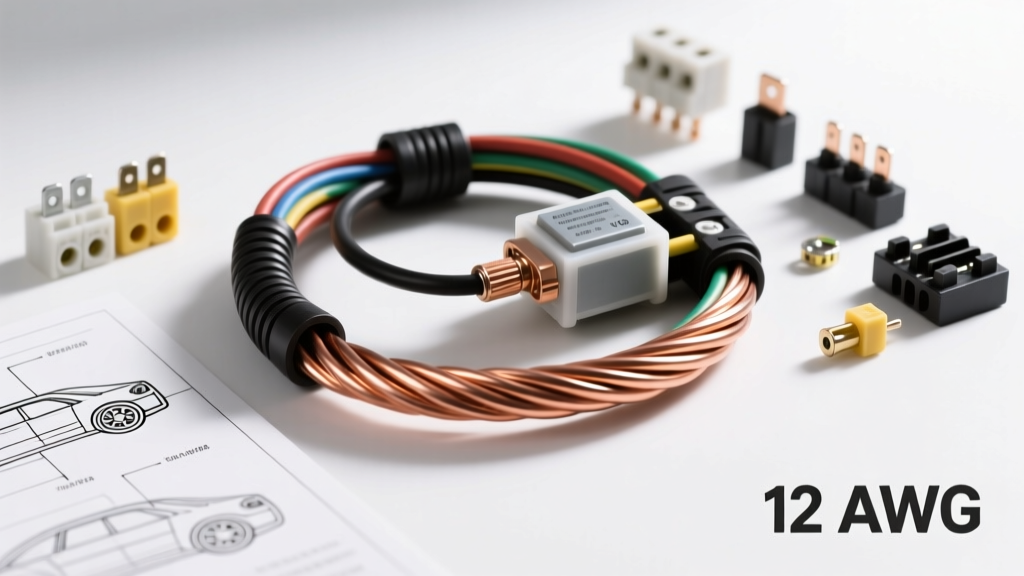
The Truth About 12 Gauge Wire Max Amps in Automotive Use
When building or modifying a vehicle's electrical system, understanding the true capacity of your conductors is critical for safety and performance. The search for the 12 gauge wire max amps often yields conflicting information because residential electrical codes (NEC) and automotive engineering standards (SAE) measure capacity differently. In a residential setting, 12 AWG copper wire is strictly limited to 20 amps. However, under the hood of a vehicle, the rules change dramatically based on insulation type, ambient temperature, and circuit length.
Automotive chassis wiring relies on SAE J1128 standards. A high-quality 12 AWG wire with TXL (Thin Wall Cross-Linked Polyethylene) insulation can safely handle up to 41 amps in a single-wire, free-air configuration at temperatures up to 125°C. However, this thermal rating does not account for voltage drop. In a 12-volt nominal system (operating at 13.8V to 14.4V with the alternator running), exceeding 20 to 25 continuous amps over long distances will result in unacceptable voltage drop, starving components like high-pressure fuel pumps or heavy-duty cooling fans of the voltage they need to operate efficiently.
Technical Specifications: 12 AWG Ampacity & Voltage Drop
To properly size your circuit, you must calculate both the thermal limit and the voltage drop limit. The Society of Automotive Engineers recommends a maximum voltage drop of 3% (approximately 0.36V on a 12V circuit) for sensitive electronics, and up to 5% for heavy motors. The table below outlines the practical continuous amp limits for 12 AWG TXL wire based on total circuit length (power + ground) to maintain a safe 3% voltage drop.
| Total Wire Length (ft) | Max Continuous Amps (12V System, 3% Drop) | Max Continuous Amps (14V System, 3% Drop) | Resistance (Ohms/1000ft) |
|---|---|---|---|
| 5 | 38A | 44A | 1.588 |
| 10 | 19A | 22A | 1.588 |
| 15 | 12.5A | 14.5A | 1.588 |
| 20 | 9.5A | 11A | 1.588 |
Note: Always use TXL, GXL, or SXL cross-linked insulation for under-hood applications. Standard PVC wire will become brittle and melt near exhaust components.
Step-by-Step Installation Guide: High-Current Fuel Pump Circuit
Let’s apply the 12 gauge wire max amps data to a real-world scenario: installing a high-flow aftermarket fuel pump (e.g., Walbro 450 or AEM 320) that draws approximately 15 to 18 amps continuously under load. Because the run from the battery to the trunk exceeds 15 feet, 12 AWG is the perfect choice to keep voltage drop under 2% while handling the thermal load safely.
Step 1: Sizing the Fuse and Relay
Never run a high-amp circuit directly through a dashboard switch. You must use a standard Bosch-style 5-pin relay (or a sealed Metri-Pack 280 series relay) to handle the heavy current.
- Relay Pinout: Pin 30 (12V Battery Input), Pin 87 (Output to Fuel Pump), Pin 85 (Switched 12V Trigger), Pin 86 (Ground).
- Fuse Sizing: Install a 25-amp MAXI or MIDI fuse on the main power feed (Pin 30) within 6 inches of the battery positive terminal. This protects the 12 AWG wire from short-circuit fires while allowing the 18-amp fuel pump to operate without nuisance blows.
Step 2: Routing and Looming the 12 AWG Harness
Route the 12 AWG power wire along the vehicle's existing chassis harness. Avoid sharp metal edges and maintain at least a 4-inch clearance from exhaust manifolds and headers.
- Use adhesive-lined split loom tubing to protect the wire from abrasion and road debris.
- Secure the loom every 12 inches using UV-resistant zip ties or factory-style push-pin retainers.
- When passing through the trunk pan or firewall, use a rubber grommet. Never let bare wire rest against sheet metal, as vibration will eventually wear through the TXL insulation and cause a dead short.
Step 3: Crimping and Sealing Terminals
The most common cause of electrical failure in high-amp circuits is a poorly crimped terminal. Soldering alone is forbidden in automotive chassis wiring because solder joints become brittle and crack under engine vibration.
- Strip the Wire: Use a precision wire stripper to remove exactly 5/16" of insulation. Do not nick the copper strands, as this reduces the cross-sectional area and creates a localized hot spot.
- Indent Crimping: Use a ratcheting crimp tool (such as an IWISS or Molex) designed for non-insulated open-barrel terminals. The tool should form a deep indent in the wire barrel and a tighter indent in the insulation barrel.
- Seal the Connection: Slide a piece of 3:1 ratio dual-wall, adhesive-lined heat shrink over the terminal. Apply heat evenly until the tubing shrinks and the inner adhesive melts and oozes out the ends. This creates a waterproof seal that prevents galvanic corrosion inside the copper strands.
Common Failure Modes and Troubleshooting
Even with the correct 12 gauge wire max amps calculations, installation errors can cause system failures. Use this decision tree to diagnose common issues:
- Symptom: Fuel pump whines loudly and engine loses power under heavy throttle.
Cause: Severe voltage drop at the pump. The pump is receiving less than 11V, causing it to over-amp and overheat.
Fix: Check the chassis ground. Remove the ground ring terminal, sand the chassis down to bare metal using 80-grit sandpaper, reattach using a star washer, and torque to 10 lb-ft. Coat the exterior with dielectric grease to prevent rust. - Symptom: Relay clicks rapidly or melts the plastic housing.
Cause: High resistance at the relay socket pins due to undersized female spade terminals or oxidation.
Fix: Replace the relay socket. Use a Metri-Pack 280 series sealed connector kit rather than standard unsealed spade slides. Apply a small amount of OxGard or conductive grease to the relay pins before insertion. - Symptom: Fuse blows only when the engine is hot.
Cause: Heat soak increasing the resistance of a failing fuel pump motor, causing amp draw to spike above the 25A fuse limit.
Fix: Measure the actual amp draw using a DC clamp meter at the battery feed while the engine is at operating temperature. If the draw exceeds 22A, the pump is failing or the fuel filter is severely restricted.
Authoritative References
For deeper engineering data on automotive wire sizing, always consult primary industry standards rather than generic forums. The following resources are essential for professional automotive electricians:
- SAE International J1128 - Standard for Low Tension Primary Cable for surface vehicle electrical systems, detailing thermal ratings and insulation requirements.
- Painless Performance Wiring Guide - Comprehensive automotive routing, crimping, and relay logic documentation.
- Madsen Enterprises Voltage Drop Calculator - Industry-standard calculator for determining exact voltage drop based on AWG, length, and specific copper temperature coefficients.