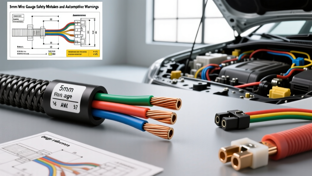
The Danger of the "5mm Wire Gauge" Misconception
When automotive enthusiasts and technicians search for a 5mm wire gauge, they are usually encountering a critical terminology crossover between Imperial (AWG) and Metric (ISO/DIN) standards. In the automotive electrical world, the term "5mm wire gauge" is technically a misnomer that leads to severe safety hazards. Wire sizing in the metric system is defined by cross-sectional area (mm²), not linear diameter. Confusing a 5mm² cross-sectional wire with a wire that has a 5mm outer diameter is one of the most common and dangerous mistakes in custom automotive wiring.
A true 5mm² wire has a cross-sectional area of 5 square millimeters, which translates to approximately 10 AWG (5.26 mm²) in the American Wire Gauge system. However, a wire with a 5mm diameter has a cross-sectional area of roughly 19.6 mm², which is closer to 5 AWG. If a builder misinterprets a schematic calling for a 5mm diameter battery cable and instead installs a 5mm² (10 AWG) primary wire, the result will be catastrophic insulation meltdown, voltage starvation, and potentially an electrical fire. This guide details the most common safety warnings, failure modes, and technical specifications you must know when working with 5mm² metric automotive wire.
Mistake #1: Confusing Metric Cross-Section (mm²) with AWG
European and Asian vehicles (following ISO 6722-1 and DIN standards) utilize metric cross-sectional sizing. North American vehicles and aftermarket components largely rely on SAE J1128 AWG standards. While 5mm² is often casually rounded to 10 AWG in aftermarket conversion charts, the physical differences matter in high-draw circuits.
- 5mm² Metric Wire: ~5.00 mm² area, ~2.52mm conductor diameter, typically 105 to 125 strands of 0.25mm copper.
- 10 AWG (SAE): ~5.26 mm² area, ~2.59mm conductor diameter, typically 105 strands of 0.254mm copper.
The Safety Warning: While 5mm² and 10 AWG are close enough for general 12V lighting circuits, they are not identical. If you are sizing wire for a continuous 40A load (like an electric water pump or dual cooling fans), 5mm² wire operating at its absolute thermal limit will experience higher resistance than a true 10 AWG wire. Always round up to the next AWG size (8 AWG / 8mm²) if your calculated load sits on the boundary between 10 AWG and 5mm².
Mistake #2: Ignoring Voltage Drop in Long Chassis Runs
A 5mm² (10 AWG) wire is perfectly adequate for a 30A circuit if the wire run is short. However, many custom wiring harness builders use 5mm² wire to run power from the front-mounted battery to a rear-mounted fuel cell surge tank or electric trailer brake controller. Over long distances, the resistance of the copper causes significant voltage drop, leading to component failure and wire heating.
Voltage Drop Reference Chart: 5mm² (10 AWG) Copper at 12V Nominal
| Current Draw (Amps) | 1-Way Run: 5 Feet (10ft Round Trip) | 1-Way Run: 10 Feet (20ft Round Trip) | 1-Way Run: 20 Feet (40ft Round Trip) |
|---|---|---|---|
| 10A (e.g., Fuel Pump) | 0.10V (Excellent) | 0.20V (Acceptable) | 0.40V (Marginal) |
| 20A (e.g., Headlights) | 0.20V (Excellent) | 0.40V (Acceptable) | 0.80V (Poor - Upgrade to 8mm²) |
| 30A (e.g., Cooling Fan) | 0.30V (Acceptable) | 0.60V (Marginal) | 1.20V (Dangerous - Fire Risk) |
| 40A (e.g., Winch Solenoid) | 0.40V (Marginal) | 0.80V (Poor) | 1.60V (Catastrophic Failure) |
Note: Data derived from standard copper resistance calculations via The Engineering Toolbox. Automotive charging systems operate at 13.8V to 14.4V, but a drop below 11.5V at the component will cause relays to chatter and motors to overheat due to amperage spikes.
Mistake #3: Mismatching Metric Wire to Imperial Crimp Terminals
One of the most frequent causes of high-resistance connections in custom harnesses is cramming metric FLRY (flexible low-voltage) wire into standard AWG ring terminals. Metric wire stranding is optimized for flexibility in tight engine bay looms, meaning the overall bundle diameter of a 5mm² wire might be slightly smaller or more compressible than a stiff SAE 10 AWG wire.
The Crimping Failure Mode
If you use a standard ratcheting AWG crimper on a 5mm² metric wire inserted into a 10 AWG terminal barrel, the crimper will compress the barrel to the exact dimensions of a 5.26mm² solid mass. Because the 5mm² wire lacks that extra 0.26mm² of copper volume, the crimp will be loose. Under the hood, thermal expansion and engine vibration will cause the wire to pull out of the terminal, resulting in an arc flash.
The Fix: When terminating 5mm² metric wire, use DIN 46235 metric tube terminals or specialized metric crimp dies. If you must use standard AWG terminals, fold the stripped wire back on itself once to increase the copper density inside the barrel before crimping, and always seal the connection with adhesive-lined dual-wall heat shrink to prevent moisture-induced galvanic corrosion.
Mistake #4: Overlooking Insulation Temperature Ratings
Wire gauge only dictates the current-carrying capacity of the copper conductor. It does nothing to protect the circuit if the insulation melts against a hot exhaust manifold or engine block. Standard PVC wire (often sold cheaply at hardware stores) has a maximum temperature rating of 80°C to 90°C. In an automotive engine bay, ambient temperatures frequently exceed 100°C, and localized radiant heat can push past 125°C.
- TXL / GXL (SAE J1128): Cross-linked polyethylene insulation. Rated for 125°C. GXL has a thinner wall, allowing more wire in a tight loom. Excellent for 5mm² engine bay routing.
- FLRY-B (ISO 6722): Thin-wall PVC metric wire. Rated for 105°C. Great for interior cabin wiring, dashboard clusters, and trunk routing, but unsafe for direct engine bay exposure without heavy corrugated loom shielding.
- SXL: Extra-thick cross-linked insulation. Rated for 125°C. Best for high-vibration areas where abrasion against the chassis is a risk.
Real-World Troubleshooting: The ISO Mini Relay Meltdown
A common failure we diagnose at Autoflowwire involves standard 40A ISO mini relays melting at the connector base. The root cause is almost always the misuse of 5mm² wire on the high-current pins without accounting for continuous vs. peak loads.
Standard ISO Mini Relay Pinout & Wire Sizing
- Pin 30 (Common / 12V+ In): Requires 5mm² (10 AWG) wire. Typically Red or Red/White.
- Pin 87 (Normally Open / 12V+ Out): Requires 5mm² (10 AWG) wire. Typically Blue or Blue/White.
- Pin 85 (Coil Ground): Requires 1.5mm² (16 AWG) wire. Typically Black.
- Pin 86 (Coil 12V+ Trigger): Requires 1.5mm² (16 AWG) wire. Typically Green or Yellow.
The Failure: A builder wires a pair of 20A cooling fans (40A total continuous draw) through a single 40A relay using 5mm² wire. The relay is rated for a 40A peak, but only a 20A continuous load. The 5mm² wire handles the current, but the relay's internal copper contacts overheat, transferring thermal energy down the wire and melting the plastic relay socket. Rule of thumb: Never run a continuous load exceeding 60% of a relay's peak rating. For a 40A continuous fan load, use dual relays with 8mm² (8 AWG) wire on Pins 30 and 87.
Safety Checklist for 5mm² Automotive Wiring
- Verify the Standard: Confirm if your schematic requires 5mm² (metric area) or a 5mm outer diameter cable.
- Calculate the Round-Trip: Measure the total wire length from the power source, to the component, and back to the chassis ground. Use this total length for voltage drop calculations.
- Match the Crimp Tool: Use a hex-crimp or indent-crimp tool calibrated for metric DIN terminals if utilizing FLRY wire.
- Check the Insulation: Ensure the wire jacket is rated for at least 125°C (GXL/TXL) if routed anywhere near the exhaust, headers, or radiator fans.
- Protect the Circuit: A 5mm² wire should be protected by a MAXI or MIDI fuse rated no higher than 40A, placed within 7 inches of the power distribution source.