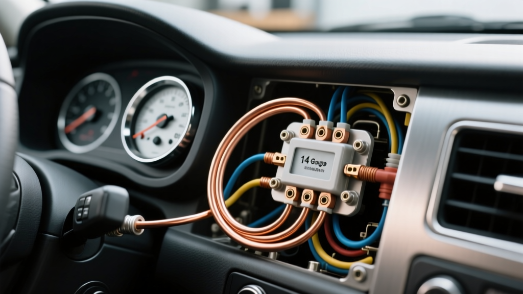
The Role of 14 AWG Solid Copper in Automotive Wiring
When building custom automotive electrical systems, the debate between stranded and solid core wire is a frequent point of contention. According to the SAE J1128 Low Tension Primary Cable Standard, stranded wire is the mandated standard for general automotive chassis and engine bay wiring due to its superior resistance to vibration-induced fatigue. However, 14 gauge solid copper wire holds a highly specific, critical role in automotive applications: rigid terminal connections, custom printed circuit board (PCB) gauge clusters, and stationary interior dash harnesses where wire flexibility is not required.
This practical installation guide focuses on the precise methodology for integrating 14 AWG solid copper wire into custom digital dash clusters, interior switch panels, and rigid terminal blocks. Using solid wire in these specific applications provides superior push-force for pin-and-socket connectors and prevents the 'splaying' of strands that often causes short circuits in tight dash cavities.
14 AWG Solid vs. Stranded: Technical Specifications
Understanding the metallurgical and electrical differences between solid and stranded 14 AWG wire is essential for calculating voltage drop and selecting the correct termination hardware. While the overall American Wire Gauge (AWG) cross-sectional area remains constant, the physical packaging alters the wire's behavior.
| Specification | 14 AWG Solid Copper | 14 AWG Stranded (19/0.0142) |
|---|---|---|
| Overall Diameter | 0.0641 inches (1.63 mm) | 0.0730 inches (1.85 mm) |
| Cross-Sectional Area | 2.08 mm² | 2.08 mm² |
| Resistance @ 20°C | 2.525 Ω / 1000 ft | 2.580 Ω / 1000 ft |
| Max Ampacity (Chassis) | 15 Amps (Continuous) | 15 Amps (Continuous) |
| Vibration Tolerance | Low (Prone to work-hardening) | High (Flexible) |
Voltage Drop Calculations for Dash Harnesses
Modern digital gauge clusters (such as Dakota Digital RTX or AutoMeter Elite series) draw significant current during startup, often peaking at 8 to 10 amps. Using the baseline resistance of 2.525 ohms per 1,000 feet, we can calculate the voltage drop for a typical 10-foot dash harness run (20 feet total round-trip for power and ground).
Formula: Voltage Drop = Current × (2 × Length × Resistance per ft)
Calculation: 10A × (20 ft × 0.002525 Ω) = 0.505 Volts.
A half-volt drop on a 12V system is acceptable, but if undersized wire is used, the cluster's internal voltage regulator may brown out, causing the screen to reboot while cranking the engine. 14 gauge solid copper wire provides the exact necessary mass to prevent this voltage sag.
Step-by-Step Installation: Custom Gauge Cluster Harness
The following procedure details the proper preparation, termination, and routing of 14 AWG solid copper wire for an aftermarket digital dash installation. Standard automotive open-barrel crimps are designed for stranded wire; using them on solid wire will result in a loose connection that arcs under load. We will use the solder-and-adhesive-seal method to ensure a permanent, vibration-proof bond.
Step 1: Precision Stripping Without Nicking
Solid copper wire is highly susceptible to 'notching' during the stripping process. A nick in the solid core creates a stress riser that will snap under minimal vibration.
- Tool Selection: Use a dedicated solid-wire stripper (e.g., Klein Tools 11055) calibrated exactly for 14 AWG. Never use the 'serrated' jaw strippers meant for Romex household wire, as they score the copper.
- Strip Length: Remove exactly 3/8-inch (9.5mm) of insulation. For 14 AWG solid wire, the insulation is typically PVC or cross-linked polyethylene (XLPE). XLPE requires more stripping force but offers superior heat resistance near the dash HVAC ducts.
Step 2: Terminal Selection and The Open-Barrel Problem
Most automotive connectors (Delphi Packard 280 series, Molex MX150) utilize open-barrel brass crimps. These rely on the stranded wire compressing and splaying outward to lock into the terminal wings. Solid wire does not splay; it remains rigid, leading to a false crimp that pulls out under tension.
- The Solution: For 14 AWG solid wire, utilize closed-barrel terminals (often found in Molex or TE Connectivity amp-inmate series) or bypass crimping entirely by using PCB-edge connectors that the solid wire solders directly into.
- Switch Panel Integration: If terminating to a rigid toggle switch panel (like a Bussmann fuse block or Carling V-Series rocker), use closed-ring terminals (e.g., 3M Highland 8000 series) specifically rated for solid wire.
Step 3: Soldering and Adhesive Heat Shrink
Because mechanical crimping is unreliable for solid core wire in vibrating environments, soldering is mandatory for chassis-side terminations.
- Pre-Tin the Wire: Apply a small amount of rosin-core solder (60/40 or SAC305 lead-free) to the exposed 3/8-inch solid copper core. Do not let the solder wick up under the insulation, as this creates a rigid 'fulcrum' point where the wire will snap.
- Solder to Terminal: Feed the pre-tinned solid wire through the closed-barrel terminal or solder cup. Apply heat with a 40W iron until the solder flows smoothly. Avoid overheating, which can melt the PVC insulation.
- Adhesive Heat Shrink: Slide a piece of dual-wall, adhesive-lined heat shrink (e.g., 3M FP-301, 1/4-inch diameter) over the joint. Apply heat evenly. The inner thermoplastic adhesive will melt and extrude from the ends, creating a waterproof, strain-relieving seal that locks the rigid solid wire to the flexible terminal.
Step 4: Routing and Vibration Isolation
When routing 14 AWG solid copper wire behind the dash, it must be treated as a rigid bus-bar rather than a flexible cable.
- Color Coding: Adhere to SAE and aftermarket standards. Use Red for 12V Constant (Battery), Pink for 12V Switched (Ignition), Black for Ground, and Orange for Dash Illumination.
- Support Bracketing: Secure the solid wire harness every 6 inches using adhesive-backed zip tie mounts. Do not pull the wire taut; leave a slight 1/2-inch loop at every termination point to absorb dash flex and engine harmonic vibration.
- Grommet Protection: If the solid wire passes through the steel firewall or a stamped steel dash brace, a rubber grommet is mandatory. The rigid nature of solid wire means it will not bend away from sharp metal edges during chassis flex, leading to immediate insulation puncture and dead shorts.
Common Failure Modes and Troubleshooting
Even when installed correctly, 14 AWG solid copper wire presents unique failure modes in automotive environments. Use this decision tree to diagnose dash electrical faults.
| Symptom | Underlying Cause | Corrective Action |
|---|---|---|
| Gauge cluster reboots during engine crank | Voltage drop due to micro-fractures in the solid 14 AWG ground wire causing high resistance. | Inspect ground termination for work-hardening. Replace with stranded 14 AWG if routing requires tight bends. |
| Intermittent dash illumination (Orange wire) | Solid core wire snapped inside the insulation at the terminal crimp due to vibration fatigue. | Cut back 1 inch, re-strip, and apply adhesive heat shrink to create a flexible strain relief boot. |
| Melted insulation near HVAC ducts | Standard PVC solid wire used in high-heat zone; PVC softens at 80°C. | Replace with 14 AWG solid wire featuring XLPE (Cross-Linked Polyethylene) insulation rated for 125°C. |
When to Transition to Stranded Wire
While 14 gauge solid copper wire is exceptional for rigid PCB pins, switch panels, and straight-line dash runs, it must never be used in applications requiring repetitive flexing. If your harness routes through the steering column shroud, door hinges, or trunk lid, you must transition to 14 AWG stranded wire. Use a solder-seal butt splice (Raychem SolderSleeve) to join the solid dash harness to the flexible chassis harness, ensuring the heat shrink encapsulates the rigid-to-flexible transition point to prevent stress concentration.
Authoritative References
- SAE International: J1128 Low Tension Primary Cable Standard - Guidelines for automotive wire insulation, temperature ratings, and stranded vs. solid applications.
- NFPA 70: National Electrical Code (NEC) - Baseline ampacity tables and voltage drop calculations for copper conductors.