Understanding the Core Question: How Does Wire Gauge Work?
When automotive enthusiasts and technicians ask, "how does wire gauge work," the answer bridges basic physics and practical electrical engineering. In a standard 12-volt (14.4V running) automotive system, wire gauge dictates the physical cross-sectional area of the conductor, which directly determines its electrical resistance and current-carrying capacity (ampacity). Unlike household AC wiring, automotive DC systems operate at low voltage, meaning they require exponentially higher amperage to deliver the same wattage. High amperage generates heat; if the wire gauge is too thin (too high a gauge number), resistance increases, resulting in severe voltage drop, melted insulation, and potential electrical fires.
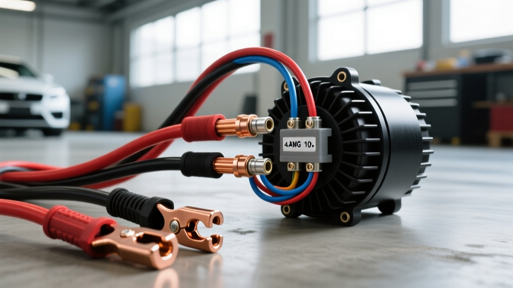
This practical installation guide answers the question of how does wire gauge work by demonstrating it in the real world. We will walk through upgrading a GM LS-platform truck's alternator output wire from the factory 8 AWG to a high-capacity 4 AWG Oxygen-Free Copper (OFC) cable, followed by wiring a 40A off-road LED light bar using a standard ISO mini relay. By the end of this guide, you will understand exactly why specific gauge sizes are mandated for specific automotive circuits.
The Physics: AWG, Circular Mils, and DC Resistance
The American Wire Gauge (AWG) system is logarithmic and inverse: a smaller gauge number means a physically thicker wire. For example, 4 AWG wire is significantly thicker than 10 AWG wire. The cross-sectional area is measured in Circular Mils (CMA). According to MAD Electrical's comprehensive wire gauge technical data, a 4 AWG wire possesses a CMA of roughly 41,740, allowing it to safely handle 100+ amps over short distances, whereas a 10 AWG wire (CMA of 10,380) is limited to roughly 30 amps.
In automotive applications, the length of the wire run is just as critical as the amperage. Because DC voltage drop is cumulative over distance, a 15-foot run of 10 AWG wire will suffer a much larger voltage drop than a 3-foot run of the same wire. This is why the factory battery-to-starter cable is often 1/0 AWG (over 100,000 CMA), while the radio memory wire is 18 AWG.
Sizing the Alternator Upgrade: 4 AWG vs. 8 AWG
Modern GM trucks (such as the Silverado 1500 with the 5.3L V8) often use the AD244 or CS130D alternator. While factory alternators produce 105A to 130A, off-road builds with winches, light bars, and auxiliary fuel pumps often require a 200A+ aftermarket upgrade. The factory 8 AWG charge wire will bottleneck a 200A alternator, causing the wire to overheat and the battery to undercharge.
| Alternator Output (Amps) | Wire Length (Under 15 ft) | Wire Length (15 - 25 ft) | Minimum Fuse/Breaker |
|---|---|---|---|
| 100A - 130A | 8 AWG | 4 AWG | 150A Mega-Fuse |
| 140A - 170A | 4 AWG | 2 AWG | 200A ANL Fuse |
| 180A - 220A | 2 AWG or 1/0 AWG | 1/0 AWG | 250A ANL Fuse |
Step-by-Step Installation: 4 AWG Alternator Charge Wire
To properly install a 4 AWG alternator charge wire, you must use the correct terminals, crimping tools, and torque specifications. Never use solder on high-amperage automotive battery or alternator terminals; solder can melt under high resistance heat and cause the connection to fail. Instead, use heavy-duty closed-barrel copper lugs and adhesive-lined heat shrink.
Materials Required
- 4 AWG Oxygen-Free Copper (OFC) primary wire (Red)
- 4 AWG to 3/8" (M10) closed-barrel copper ring terminal
- 4 AWG to 5/16" (M8) copper ring terminal (for alternator BAT post)
- Adhesive-lined polyolefin heat shrink tubing (3M or Ancor brand)
- Heavy-duty ratchet crimper or hydraulic crimping tool
- 150A ANL fuse holder and fuse
Execution Steps
- Disconnect the Battery: Always remove the negative battery terminal first to prevent a dead short across the chassis while working near the alternator.
- Measure and Cut: Route the 4 AWG OFC wire from the alternator BAT terminal to the positive battery post or main distribution block. Leave 2 inches of slack for engine movement on the motor mounts.
- Strip and Crimp: Strip exactly 3/4" of insulation from the wire ends. Insert the bare copper into the closed-barrel terminal. Use the hydraulic crimper to compress the barrel until the die fully closes, ensuring a cold-weld gas-tight connection.
- Seal the Connection: Slide the adhesive-lined heat shrink over the crimp barrel. Apply heat with a heat gun until the adhesive oozes out the ends, creating a waterproof seal against galvanic corrosion.
- Install the Fuse: Splice the 150A ANL fuse holder into the 4 AWG wire within 18 inches of the battery positive terminal. This protects the entire run in the event of a short to ground.
- Torque the Alternator Terminal: Attach the M8 ring terminal to the GM AD244 alternator BAT post. According to SAE J1128 low-tension cable guidelines and GM service manuals, the M8 alternator nut must be torqued to exactly 9 Nm (80 lb-in). Over-torquing will strip the soft brass threads on the alternator diode bridge; under-torquing will cause arcing and heat.
- Connect to Battery: Attach the M10 terminal to the positive battery post and torque to 12 Nm.
Sizing the Accessory Circuit: 10 AWG Relay Wiring for a 40A Light Bar
Understanding how does wire gauge work also applies to switched accessory circuits. A 40A LED light bar cannot be wired directly to a dashboard switch; the switch would melt. Instead, we use a standard Bosch-style ISO 5-pin mini relay to separate the high-amperage load circuit from the low-amperage trigger circuit.
| Relay Pin | Function | Wire Gauge | Wire Color | Fuse Protection |
|---|---|---|---|---|
| 30 | Constant 12V+ Power Source | 10 AWG | Red | 40A Blade Fuse |
| 87 | Load Output (to Light Bar +) | 10 AWG | Blue | None (Protected by Pin 30) |
| 85 | Coil Ground | 16 AWG | Black | None |
| 86 | Switched 12V+ Trigger | 16 AWG | Yellow | 5A Tap Fuse |
| 87a | Normally Closed (Unused) | N/A | N/A | N/A |
Notice the gauge disparity: Pins 30 and 87 carry the full 40A load, requiring 10 AWG wire. Pins 85 and 86 only power the internal electromagnetic coil of the relay, which draws less than 150 milliamps (0.15A). Therefore, 16 AWG wire is more than sufficient for the trigger circuit, saving weight, cost, and making the wires easier to route through the firewall grommet.
Voltage Drop Testing: Proving the Gauge Works
The ultimate proof of how does wire gauge work in practice is the voltage drop test. Even if a wire is rated for a specific amperage, a poor crimp or a corroded terminal will introduce resistance. To verify your 4 AWG alternator upgrade and 10 AWG relay wiring:
- Set your digital multimeter to DC Volts.
- Start the engine and turn on all electrical loads (headlights, blower motor on high, light bar on) to force the alternator to output maximum amperage.
- Place the red probe on the alternator BAT terminal and the black probe on the positive battery post.
- Evaluate the Reading: A healthy 4 AWG cable run should show a voltage drop of less than 0.2V. If the meter reads 0.5V or higher, you have excessive resistance. This indicates a failing crimp, a wire gauge that is too small for the actual amperage draw, or corrosion inside the terminal.
Summary: Matching Physics to Application
Understanding how does wire gauge work is the foundation of reliable automotive electrical modifications. By respecting the physical limits of AWG sizing, utilizing proper cold-weld crimping techniques, and verifying your work with voltage drop testing, you ensure that your vehicle's electrical system operates safely and efficiently. Whether you are routing 1/0 AWG battery cables or 18 AWG sensor grounds, the principles of DC resistance and circular mil area remain your ultimate guide. For further reading on high-current automotive wiring standards, refer to the Bosch Mobility Solutions vehicle electrical systems documentation to ensure your builds meet OEM-level reliability.