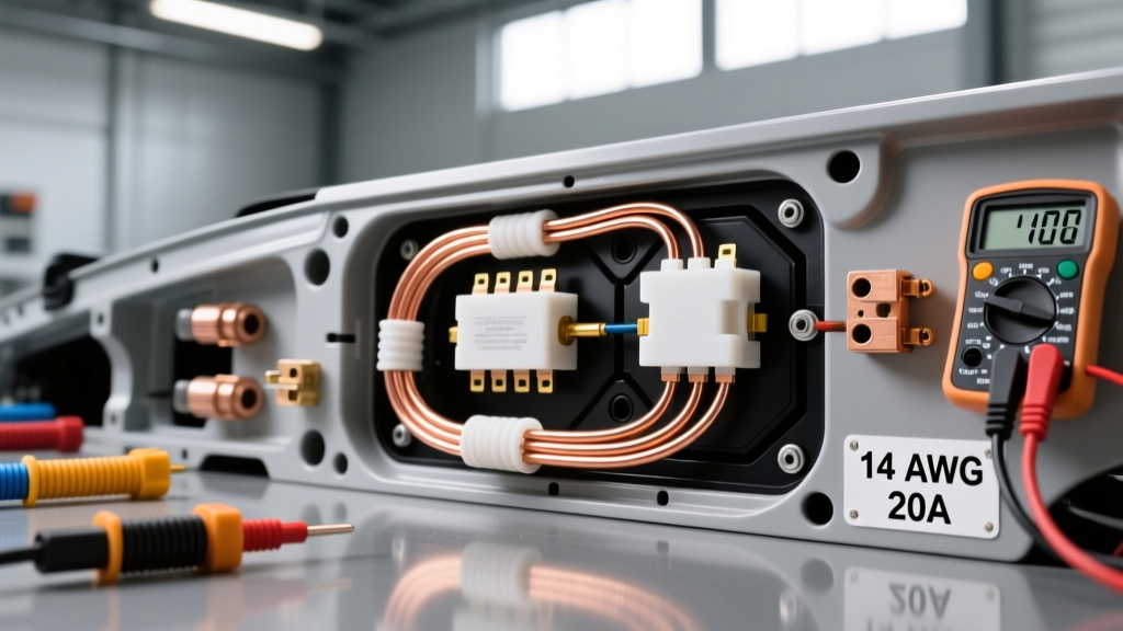
The Short Answer: Will 14 Gauge Wire Handle 20 Amps?
When enthusiasts and technicians ask, "will 14 gauge wire handle 20 amps?" the internet is flooded with conflicting information. The short answer is: Technically yes, for very short, free-air runs under ideal conditions, but practically NO for continuous 20-amp automotive loads. Relying on 14 AWG wire for a 20-amp circuit in a vehicle is one of the most common and dangerous mistakes in aftermarket automotive electrical work. It leads to severe voltage drop, melted insulation, connector degradation, and in worst-case scenarios, electrical fires.
To understand why 14 AWG is insufficient for 20 amps in a real-world vehicle, we must separate household electrical codes from automotive SAE standards, examine ambient temperature derating, and look at real-world failure modes like aftermarket fuel pump installations.
The "Free Air" Myth vs. Engine Bay Reality
The confusion usually stems from misinterpreted SAE J1128 ampacity charts. Many online forums cite charts showing 14 AWG wire handling up to 25 amps. However, these charts come with critical caveats that are almost never mentioned:
- Ambient Temperature: The baseline chart assumes an ambient temperature of 25°C (77°F). Engine bays routinely exceed 100°C (212°F), and under-hood wiring looms can easily see 125°C.
- Free Air vs. Bundled: The chart assumes a single wire suspended in free air with unlimited convective cooling. In a car, wires are bundled in corrugated looms, wrapped in Tesa tape, and zip-tied against hot chassis components.
- Insulation Type: The higher ampacities assume high-temperature cross-linked polyethylene (XLPE) insulation like GXL or TXL, not cheap hardware-store PVC wire.
Common Mistake #1: Ignoring Temperature Derating
According to SAE derating curves, as ambient temperature rises, the current-carrying capacity of the wire plummets. If you are routing a 20-amp cooling fan circuit through the radiator support where ambient temperatures hit 85°C, the ampacity of 14 AWG GXL wire drops by roughly 30%. A wire rated for 25 amps at room temperature is now safely limited to roughly 17.5 amps. Pushing 20 amps through this wire will cause the copper to heat up, softening the insulation and eventually causing a short circuit against the chassis.
Common Mistake #2: Confusing NEC with SAE Standards
Electricians often chime in citing the National Electrical Code (NEC) Article 310, which strictly limits 14 AWG copper to 15 amps. While the NEC applies to 120V/240V AC household wiring and factors in extreme safety margins for continuous loads inside insulated walls, automotive DC systems operate at 12V-14.4V. In automotive systems, voltage drop is often the limiting factor before thermal melting occurs. A 15-amp NEC limit isn't the exact automotive rule, but it highlights the danger of pushing 20 amps through a 2.525-ohm-per-1000ft conductor.
Real-World Failure Modes: When 14 AWG Melts
To illustrate the danger, let us examine a highly common modification: upgrading to a high-flow aftermarket fuel pump, such as a Walbro 255lph or AEM 340lph.
Case Study: Aftermarket Fuel Pump Wiring
A common mistake is using the factory 14 AWG fuel pump wiring harness to power a new high-performance pump. The factory pump may have only drawn 8 to 10 amps, making 14 AWG perfectly adequate. However, a 255lph pump pulling against 60 PSI of fuel pressure will draw between 14 and 18 amps continuously, with startup spikes exceeding 22 amps.
The Failure Sequence:
- Voltage Drop: 14 AWG wire has a resistance of 0.002525 ohms per foot. Over a 12-foot run (24 feet round trip to ground), pushing 18 amps results in a voltage drop of over 1.08 volts.
- Pump Starvation: Fuel pumps are highly sensitive to voltage. Dropping from 13.8V (alternator charging) to 12.7V at the pump connector can reduce fuel flow by 10-15%, causing lean conditions under wide-open throttle (WOT).
- Thermal Runaway: Because the pump receives lower voltage, it works harder and draws more current to meet its mechanical load. This further increases the $I^2R$ (heat) losses in the 14 AWG wire.
- Connector Melt: The factory Delphi Metri-Pack 150 or 280 connectors are not rated for continuous 20A+ loads. The increased resistance at the crimp joint generates localized heat, melting the plastic connector housing and causing an open circuit or fire.
Automotive Wire Sizing Chart: 20 Amp Circuit Requirements
When designing a 20-amp circuit (e.g., electric cooling fans, fuel pumps, winch solenoid triggers, or heavy off-road lighting), you must size the wire to keep voltage drop under 3% (0.36V on a 12V system). Below is the correct sizing matrix for a 20-amp continuous load.
| Total Wire Length (Round Trip) | 14 AWG (Voltage Drop) | 12 AWG (Voltage Drop) | 10 AWG (Voltage Drop) | Recommended Gauge |
|---|---|---|---|---|
| 5 Feet | 0.25V (1.8%) | 0.16V (1.1%) | 0.10V (0.7%) | 12 AWG (Safe Minimum) |
| 10 Feet | 0.51V (3.6%) | 0.32V (2.3%) | 0.20V (1.4%) | 12 AWG |
| 15 Feet | 0.76V (5.4%) | 0.48V (3.4%) | 0.30V (2.1%) | 10 AWG (Required) |
| 20 Feet | 1.01V (7.2%) | 0.64V (4.6%) | 0.40V (2.8%) | 10 AWG (Required) |
Note: Total Wire Length includes the distance from the power source to the load, plus the return path to the chassis ground.
As the table demonstrates, 14 AWG wire fails the 3% voltage drop rule for a 20-amp load at distances beyond 7 feet. For any 20-amp automotive circuit running from the front of the vehicle to the rear (like a fuel pump or trailer charge line), 10 AWG is the professional standard, with 12 AWG being the absolute minimum for shorter runs.
Proper Connectors and Fusing for 20A Circuits
Upgrading your wire gauge is only half the battle. A 10 AWG wire is useless if it is bottlenecked by an undersized connector or protected by an improperly placed fuse. Resources like Painless Performance emphasize that the weakest link in a DC circuit dictates its safety.
Relay Pinouts and Trigger Wiring
Never run a 20-amp load directly through a dashboard switch. You must use a high-quality 30A or 40A Bosch-style ISO mini relay. Here is where 14 AWG wire is acceptable: the relay trigger circuit.
- Pin 30 (Power In): 10 AWG or 12 AWG directly from the battery positive.
- Pin 87 (Power Out): 10 AWG or 12 AWG to the load (fuel pump/fan).
- Pin 85 (Ground): 14 AWG or 16 AWG to a clean chassis ground.
- Pin 86 (Trigger In): 14 AWG or 16 AWG from the ignition switch or ECU trigger. (This circuit draws less than 0.2 amps, making 14 AWG more than sufficient).
Terminal Crimping and Heat Shrink Specs
When terminating 12 AWG or 10 AWG wire for a 20-amp circuit, abandon solder-only connections. Solder wicks under the insulation, creating a rigid point that snaps under automotive vibration. Furthermore, solder has a higher electrical resistance than copper, generating heat at the joint.
Use a ratcheting crimp tool (such as the TE Connectivity CERTI-CRIMP or a high-quality Titan equivalent) with open-barrel or closed-barrel dies matched to the wire size. Seal the connection using dual-wall, adhesive-lined polyolefin heat shrink. The inner wall melts and flows into the wire strands, preventing moisture ingress and capillary action, which is the primary cause of green-crust corrosion and subsequent resistance spikes in engine bay wiring.
Fusing Placement and Sizing
For a continuous 20-amp load, use a 25A or 30A ATO/ATC blade fuse, or a 30A MAXI fuse. Crucially, this fuse must be located within 18 inches of the battery positive terminal. If you run an unfused 10 AWG wire 15 feet through the firewall to a fuse box inside the cabin, a chafed wire under the dash will turn that 10 AWG wire into a 200-amp glow plug, melting the harness long before the battery cable fails. Always fuse at the source.
Summary: The Golden Rule of 20-Amp Automotive Circuits
If you are still asking yourself, "will 14 gauge wire handle 20 amps?" the definitive automotive answer is to stop taking the risk. While 14 AWG might survive a 20-amp bench test in an air-conditioned room, the hostile environment of a vehicle—characterized by high ambient heat, vibration, chemical exposure, and bundled wire looms—demands a larger safety margin. Always step up to 12 AWG for short runs, and 10 AWG for runs exceeding 10 feet. Pair this with proper ratcheting crimps, adhesive-lined heat shrink, and source-side fusing to ensure your electrical system is safe, reliable, and fire-free.