Understanding AWG: Should You Use 12 or 14 Gauge Wire for Lights?
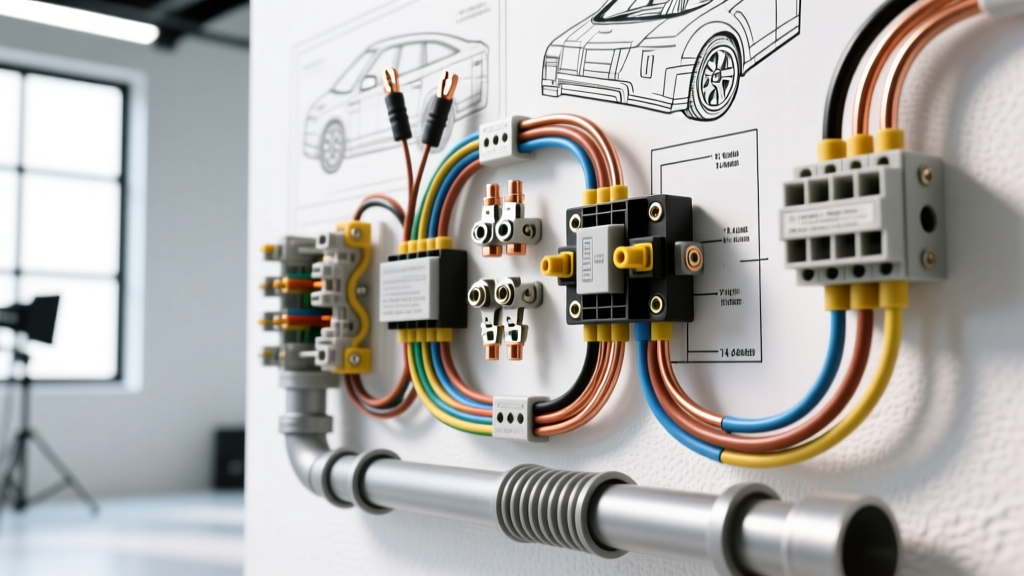
When upgrading automotive lighting—whether swapping dull factory halogens for high-output bulbs or wiring auxiliary off-road light bars—the most common question installers face is whether to use 12 or 14 gauge wire for lights. The correct answer relies on understanding circuit topology. In a professional automotive lighting installation, you rarely use just one gauge. Instead, you utilize 12 AWG for the main power feed from the battery to the relay, and 14 AWG for the branch drops from the relay to the individual light fixtures.
Factory headlight wiring is notorious for voltage drop. Automakers often use 16 or 18 AWG wire routed through the firewall, up the steering column to the headlight switch, and back out to the engine bay. This long, thin circuit path acts as a resistor, dropping the voltage at the bulb from a healthy 14.2V down to 11.5V or lower, resulting in dim, yellowish light output. By building a dedicated relay harness, you bypass the factory switch for the heavy current, using the switch only as a low-amp trigger signal.
12 AWG vs. 14 AWG Technical Specifications
According to SAE J1128 standards for automotive primary wire, GXL (General Cross-Linked) and TXL (Thin-Wall Cross-Linked) insulation types dictate the physical dimensions and thermal limits of the wire. Below is the reference chart for standard 19-strand automotive copper wire.
| AWG Size | Strand Count | Nominal O.D. (in) | Circular Mils | Max Ampacity (Chassis) | Resistance (Ohms/1000ft) |
|---|---|---|---|---|---|
| 12 AWG (TXL) | 19 | 0.090 | 6,530 | 20 Amps | 1.62 |
| 14 AWG (TXL) | 19 | 0.075 | 4,110 | 15 Amps | 2.58 |
Note: Max ampacity assumes standard under-hood ambient temperatures (up to 125°C for TXL). Bundling multiple wires inside a tight split-loom conduit reduces thermal dissipation and requires derating the ampacity by 15-20%.
Calculating Your Lighting Load
Before cutting wire, you must calculate the total amperage draw of your lighting setup. Automotive electrical systems operate nominally at 12.0V (engine off) to 14.4V (alternator charging). We use the lower 12.0V figure for conservative safety calculations.
- Standard Halogen H11 (55W): 55W / 12.0V = 4.58 Amps
- High-Beam 9005 / HB3 (65W): 65W / 12.0V = 5.41 Amps
- Upgraded 100W Off-Road Halogen: 100W / 12.0V = 8.33 Amps
- LED Replacement Bulbs (Pair): Typically 2.0 to 3.5 Amps total
If you are wiring a dual-headlight setup using standard 55W/65W halogens, the combined draw is roughly 10 Amps. A 14 AWG wire (rated for 15A) is technically sufficient for the entire circuit. However, using 12 AWG for the main battery feed ensures near-zero voltage drop over the 6-to-10 foot run from the battery terminal to the front bumper or firewall relay block. The 14 AWG is then perfectly suited for the short 2-to-3 foot drops from the relay to the left and right headlight housings.
Step-by-Step Installation Guide: Upgrading Headlight Wiring
This guide details the construction of a high-output headlight relay harness utilizing a standard Bosch-style Mini-ISO 4-pin relay. For comprehensive relay pinout specifications and load limits, refer to the Littelfuse Mini-ISO Relay Datasheet.
Step 1: Mapping the Circuit and Selecting Connectors
Never use generic 'bullet' connectors or twist-and-tape methods for automotive lighting. Vibration and moisture will cause rapid corrosion and failure. You must use sealed automotive connectors.
- Relay Connection: Use a sealed Mini-ISO relay pigtail with pre-attached wires, or crimp TE Connectivity AMP Junior Timer terminals into a sealed relay socket.
- Headlight Connection: Identify your bulb type (e.g., H4/9003, H11, 9006). Source OEM-equivalent connectors (such as Sumitomo TS 090 or Yazaki housings) with pre-crimped pigtails to splice into your 14 AWG branch wires.
- Grounding: Use a 1/4-inch (6mm) ring terminal with a serrated flange to bite through paint and ensure bare-metal contact to the chassis.
Step 2: Routing the 12 AWG Power Feed and Relay Integration
- Disconnect the Battery: Always isolate the negative terminal before beginning under-hood electrical work.
- Prepare the 12 AWG Main Feed: Cut a length of 12 AWG Red wire to reach from the positive battery terminal to your chosen relay mounting location (usually near the radiator core support or strut tower). Strip 5/16-inch of insulation.
- Install the Inline Fuse: Crimp a Maxi-Fuse or ATC fuse holder into the 12 AWG Red wire, positioned within 18 inches of the battery terminal. For a dual 65W halogen setup (approx 11A draw), install a 15A or 20A ATC fuse.
- Wire the Relay (Pin 30): Crimp the battery-side of the 12 AWG Red wire to Pin 30 (Common Input) of the Mini-ISO relay. Terminate the battery end with a 3/8-inch or 5/16-inch ring terminal, depending on your battery post stud size.
- Wire the Relay (Pin 85 & 86): Run an 18 AWG Yellow wire from Pin 86 to the factory headlight positive wire (this is your low-amp trigger signal). Run a 12 AWG Black wire from Pin 85 to a clean, unpainted chassis ground point.
Step 3: Terminating the 14 AWG Drops to the Lights
- Branch from Pin 87: Pin 87 (Normally Open Output) is where the switched power exits the relay. Crimp a 12-to-14 AWG reducing butt connector to a length of 14 AWG Red wire.
- Split the Circuit: If powering two headlights, use a sealed T-tap or a stepped crimp barrel to split the 14 AWG feed into two separate 14 AWG Red wires running to the left and right headlights.
- Splice to OEM Connectors: Use adhesive-lined heat shrink butt connectors to splice your 14 AWG Red wire to the positive wire on your OEM headlight pigtail. Crucial: The heat shrink must contain a polyamide inner liner that melts and seals the wire strands, preventing capillary action from drawing moisture into the copper.
- Protect the Loom: Slide the completed harness into 1/4-inch or 3/8-inch nylon braided sleeving (Techflex) or split corrugated loom. Secure the loom every 6 inches using UV-resistant zip ties or automotive cloth tape (Tesa 51036).
Real-World Troubleshooting & Failure Modes
Even with the correct wire gauge, automotive lighting circuits are prone to specific failure modes. Use this diagnostic tree to resolve common issues:
Symptom: Melted Headlight Connectors (Common on H4 / 9003 Bulbs)
- Cause: High resistance at the terminal crimp or using 16 AWG wire on a 65W/100W bulb. The connector acts as a heater, melting the plastic housing.
- Fix: Cut off the melted OEM connector. Replace with a high-temperature ceramic H4 connector or a heavy-duty Sumitomo housing. Ensure you are using 14 AWG wire for the final drop, and verify that the female terminals tightly grip the male bulb prongs using a terminal tension tool.
Symptom: LED Lights Flickering or Strobing (Modern Vehicles)
- Cause: This is rarely a wire gauge issue. Modern vehicles (2015+ RAM, F-150, Jeep Cherokee) use PWM (Pulse Width Modulation) to check for burnt-out bulbs. Because LEDs draw significantly less current than halogens, the CANBUS system assumes the bulb is dead and pulses the circuit or throws a dash error.
- Fix: Install CANBUS decoders (load resistors or capacitor modules) inline on the 14 AWG branch wires between the relay and the LED driver. Alternatively, use an OBD2 software tool (like AlfaOBD or FORScan) to disable the cold-check and warm-check PWM signals for the headlight circuits.
Symptom: Dim Lights Even After Relay Harness Installation
- Cause: Poor chassis ground on Pin 85, or using a ground point that shares a high-load return path (like the radiator fan ground).
- Fix: Relocate the 12 AWG Black ground wire to a dedicated grounding stud on the strut tower or inner fender. Sand away the paint and clear coat down to bare steel, apply a dab of dielectric grease after torquing the bolt to 15-20 lb-ft to prevent future galvanic corrosion.
By strategically combining 12 AWG for high-current feeds and 14 AWG for flexible branch routing, you ensure maximum lumen output, eliminate factory voltage drop, and create a lighting harness that will outlast the vehicle itself.