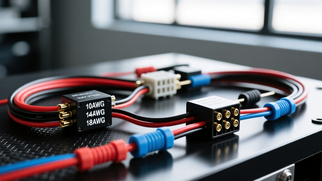
Understanding the 12 Volt Wire Gauge Chart in Automotive Contexts
When designing, repairing, or modifying automotive electrical systems, relying on a standard household wire gauge chart can lead to catastrophic failures. Automotive environments introduce high under-hood temperatures, vibration, and chemical exposure that drastically alter a wire's current-carrying capacity (ampacity). Furthermore, while we refer to these systems as '12-volt,' a running alternator pushes system voltage to 13.8V–14.4V, meaning your wiring must handle thermal loads based on continuous amperage draw, not just nominal voltage.
In this complete wiring diagram walkthrough, we will apply a strict 12 volt wire gauge chart to build a 40-amp off-road LED light bar relay harness. By analyzing each pin of a standard automotive ISO mini relay, we will calculate voltage drop, select the correct SAE J1128 primary wire, and specify the exact crimp terminals required for a factory-grade installation.
Standard 12 Volt Wire Gauge Chart (SAE J1128 vs. AWG)
The Society of Automotive Engineers (SAE) standard J1128 dictates the specifications for low-tension primary cable used in surface vehicles. Unlike the American Wire Gauge (AWG) system used in building wiring, SAE automotive wire features thinner insulation and slightly different stranding to optimize flexibility and heat dissipation. Below is the definitive reference chart for chassis wiring (under 50°C ambient) and engine bay wiring (up to 125°C ambient).
| AWG Size | SAE Metric (mm²) | Max Amps (Chassis) | Max Amps (Engine Bay) | Resistance per 1000ft (Ω) |
|---|---|---|---|---|
| 18 AWG | 0.80 mm² | 6A | 4A | 6.385 |
| 16 AWG | 1.30 mm² | 10A | 7A | 4.016 |
| 14 AWG | 2.00 mm² | 15A | 11A | 2.525 |
| 12 AWG | 3.00 mm² | 20A | 15A | 1.588 |
| 10 AWG | 5.00 mm² | 30A | 23A | 0.999 |
| 8 AWG | 8.00 mm² | 45A | 35A | 0.628 |
| 6 AWG | 13.0 mm² | 65A | 50A | 0.395 |
| 4 AWG | 19.0 mm² | 95A | 70A | 0.248 |
Note: Ampacity ratings assume a maximum allowable voltage drop of 3% for critical loads and standard cross-linked polyethylene (XLPE) insulation. For authoritative baseline data, refer to the SAE J1128 Standard for Low Tension Primary Cable.
Complete Wiring Diagram Walkthrough: 40A Off-Road Relay Harness
We are wiring a 40-inch curved LED light bar drawing 38 amps at 14.2V. The circuit utilizes a standard 5-pin Bosch-style ISO mini relay (Pins 30, 85, 86, 87, and 87a). Here is the pin-by-pin breakdown utilizing our 12 volt wire gauge chart.
Step 1: Battery to Relay (Pin 30 High-Current Feed)
Wire Selection: 8 AWG SAE Primary Wire (Red, XLPE insulation).
Why 8 AWG? The light bar draws 38A continuously. According to our chart, 10 AWG is rated for 30A in the chassis and only 23A in the engine bay. Using 10 AWG would cause the insulation to soften and melt near the relay contacts. 8 AWG provides a safe 45A chassis rating, giving us a 15% safety buffer.
Termination: At the battery, use a 5/16-inch closed-loop ring terminal with an adhesive-lined heat shrink sleeve. Crimp using a ratcheting hex-crimp tool to ensure a gas-tight connection. At Pin 30 of the relay, use a 1/4-inch female quick-disconnect terminal with a brass insert, fully insulated to prevent accidental shorting against the chassis.
Step 2: Trigger Circuit (Pin 86 Low-Current Signal)
Wire Selection: 16 AWG SAE Primary Wire (Blue).
Routing & Tapping: This wire carries less than 0.2 amps to energize the relay coil. Route this wire through the firewall grommet into the cabin. For a modern vehicle like a 2021 Jeep Wrangler JL or Toyota Tacoma, do not splice into the headlight wiring, as the multiplexed CAN-bus system will detect the resistance change and throw a BCM (Body Control Module) fault code. Instead, use an Add-A-Circuit fuse tap on an ignition-switched 12V source in the interior fuse box (e.g., the 12V accessory outlet circuit).
Protection: Install a 3A mini blade fuse at the tap point to protect the 16 AWG trigger wire from short circuits.
Step 3: Chassis Ground (Pin 85 Return Path)
Wire Selection: 16 AWG SAE Primary Wire (Black).
Grounding Protocol: The relay coil ground must be as reliable as the trigger. Locate a dedicated factory ground stud on the inner fender liner or firewall. Remove the factory nut, clean the bare metal with a Scotch-Brite pad to remove zinc plating and e-coat, and install the 16 AWG ring terminal. Re-torque the M6 ground nut to 8-10 Nm. Coat the exposed metal with dielectric grease to prevent galvanic corrosion.
Step 4: Relay to Load (Pin 87 Output Run)
Wire Selection: 10 AWG SAE Primary Wire (Red) transitioning to dual 12 AWG pigtails.
Routing & Connectors: Run the 10 AWG wire from Pin 87 to the front grille. Because the LED bar uses a split Y-harness, splice the 10 AWG main feed into two 12 AWG branches using a sealed 3-cavity Weather-Pack connector. According to the chart, 12 AWG handles 20A per branch (the 38A draw is split evenly to 19A per side), keeping us safely within limits.
Load Termination: Terminate the ends at the light bar using a 2-pin Deutsch DT plug with Size 16 solid contacts. Use the proper Deutsch wedge locks and silicone seals to guarantee an IP68 waterproof rating, preventing moisture ingress that leads to green corrosion on the copper strands.
Real-World Failure Modes & Troubleshooting
Even with a perfect 12 volt wire gauge chart reference, installations fail due to material and execution errors. Watch out for these common pitfalls:
- CCA (Copper Clad Aluminum) Wire: Many cheap aftermarket harnesses use CCA wire instead of bare copper. CCA has approximately 40% higher electrical resistance than pure copper. If you use 10 AWG CCA wire for a 35A load, it will overheat and cause a voltage drop exceeding 1.5V, resulting in a dim light bar and melted relay sockets. Always verify the wire is 100% oxygen-free copper (OFC).
- Missing Flyback Diode: When the relay coil (Pins 85/86) is de-energized, the collapsing magnetic field sends a high-voltage spike backward through the trigger wire. If your trigger source is tied to a sensitive ECU or CAN-bus module, this inductive kickback can fry the vehicle's computer. Always install a 1N4001 flyback diode across Pins 85 and 86 (stripe facing Pin 86) to suppress the voltage spike.
- Undersized Ground Paths: A relay harness is only as good as its ground. If the light bar itself is grounded to a painted aluminum bumper or a plastic radiator support bracket, the circuit will seek ground through the vehicle's data lines, causing erratic gauge cluster behavior. Always run a dedicated 10 AWG ground wire from the light bar directly back to the battery negative terminal or a verified bare-metal chassis node.
Authoritative References
For further technical validation on automotive wire sizing, voltage drop calculations, and crimp specifications, consult the following industry resources: