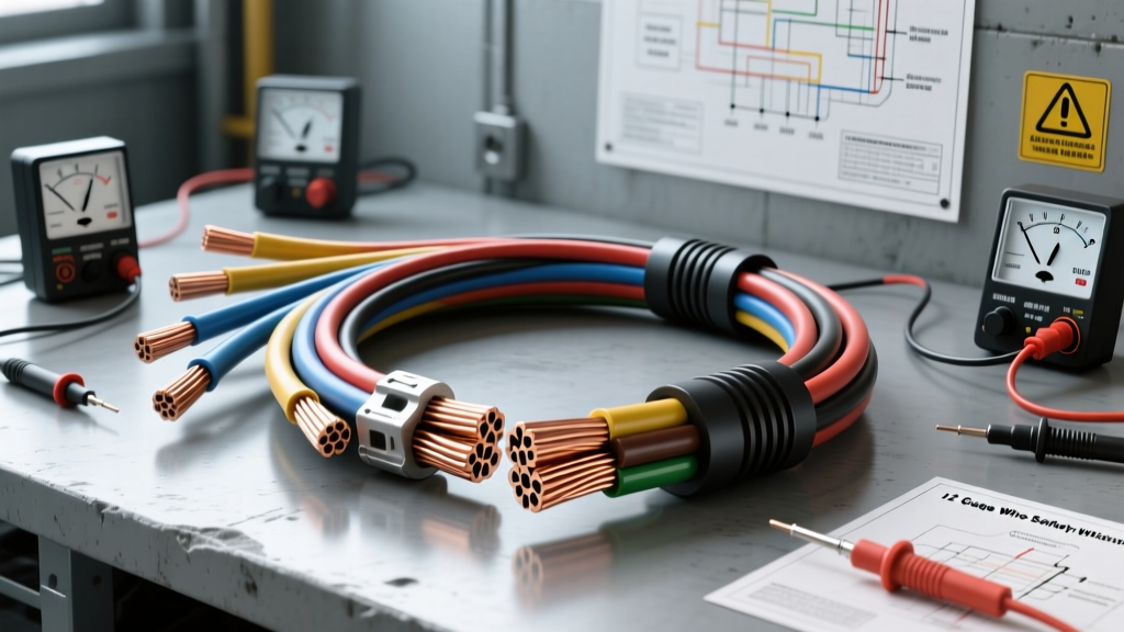
Why 12 Gauge Wire is the Most Misunderstood Automotive Conductor
In automotive electrical systems, 12 gauge wire (12 AWG) is widely considered the ultimate workhorse. With a copper diameter of 0.0808 inches and a cross-sectional area of 3.309 mm², it is the standard choice for high-draw accessories like fuel pumps, radiator cooling fans, HID ballasts, and power window motors. However, its versatility breeds complacency. Many technicians and DIY enthusiasts treat 12 AWG as a universal "medium-duty" solution, leading to catastrophic electrical fires, melted harnesses, and unexplained component failures.
At AutoflowWire, we frequently diagnose harness failures that trace back to fundamental misunderstandings of ampacity, voltage drop, and insulation ratings. Below, we detail the most dangerous safety mistakes made when working with 12 gauge wire in automotive applications, backed by engineering standards and real-world failure analysis.
Mistake #1: Ignoring SAE J1128 Temperature Derating
The most common safety warning we issue regarding 12 gauge wire involves ampacity ratings. A standard rule of thumb states that 12 AWG copper can handle 20 amps continuously. However, this assumes an ambient temperature of 77°F (25°C) and a single, unbundled wire. In a real automotive engine bay, ambient temperatures frequently exceed 125°F (51°C), and wires are tightly bundled in split-loom tubing or OEM harness wraps.
According to the SAE J1128 Standard for automotive cable, as ambient temperature and bundle density increase, the wire's ability to dissipate heat decreases. If you push 20 amps through a 12 AWG wire bundled with four other current-carrying conductors in a 105°C engine environment, the insulation will eventually soften, melt, and short against the chassis.
12 AWG Ampacity Derating Chart (Automotive GXL/TXL Insulation)
| Bundle Size (Wires) | Ambient Temp 85°F (29°C) | Ambient Temp 125°F (52°C) | Ambient Temp 158°F (70°C) |
|---|---|---|---|
| 1 (Single Wire) | 25.0 Amps | 22.0 Amps | 18.0 Amps |
| 2-3 Wires | 20.0 Amps | 17.5 Amps | 14.0 Amps |
| 4-6 Wires | 16.0 Amps | 14.0 Amps | 11.0 Amps |
| 7-12 Wires | 12.5 Amps | 11.0 Amps | 8.5 Amps |
Safety Warning: Never route 12 AWG battery feed wires inside the same loom as low-current sensor wires if the feed is drawing near its 20A peak limit.
Mistake #2: Miscalculating Voltage Drop in High-Draw Circuits
12 gauge wire has a resistance of approximately 1.588 ohms per 1,000 feet at 20°C. While this seems negligible, it becomes a critical safety and performance issue in long runs, such as trailer brake controllers, rear-mounted auxiliary fuel cells, or winch solenoid triggers.
Consider a rear-mounted Walbro 255lph fuel pump in a custom chassis. The wiring run from the front-mounted relay to the rear tank is 15 feet. Because current must travel to the load and return to ground, the total circuit length is 30 feet. At a 20-amp draw, the voltage drop is calculated as follows:
- Total Resistance: (30 ft / 1000 ft) * 1.588 ohms = 0.0476 ohms
- Voltage Drop: 20 Amps * 0.0476 ohms = 0.95 Volts
If the alternator is outputting 14.2V, the fuel pump only receives 13.25V. While this may seem acceptable, as the vehicle's charging system ages and output drops to 13.5V under heavy electrical load, the pump voltage falls below 12.5V, causing a lean fuel condition and potential engine detonation. For runs exceeding 12 feet round-trip on a 20A circuit, Pacer Group Technical Resources strongly recommends stepping up to 10 AWG wire to mitigate voltage drop and heat generation.
Mistake #3: Over-Fusing to "Stop the Blowing"
A dangerous and all-too-common garage mistake is replacing a repeatedly blowing 20A fuse with a 25A or 30A fuse because "the 12 gauge wire can handle it." This fundamentally misunderstands the purpose of a fuse. A fuse protects the wire, not the component.
If a 12 AWG wire experiences a dead short to ground, a 30A fuse may take several seconds to blow. In that timeframe, the wire will draw hundreds of amps, causing the PVC or GXL insulation to smoke, melt, and potentially ignite surrounding sound deadening or carpet. Furthermore, if the short has slight resistance (e.g., a pinched wire rubbing against a semi-conductive bracket), the current might spike to 28 amps—enough to melt the 12 AWG copper strands over time, but not enough to trip a 30A fuse. Always match the fuse to the wire's derated ampacity, utilizing slow-blow (Time-Delay) fuses only for components with high inrush currents like motors and compressors.
Mistake #4: Improper Crimping and Environmental Sealing
Using 12 gauge wire in harsh environments (wheel wells, undercarriage, engine bays) requires proper terminal selection and crimping techniques. A common failure mode occurs when technicians use standard PVC-insulated ring terminals in high-vibration or high-moisture areas.
- The Crimp Die Error: Using a generic pair of pliers to crush a 12-10 AWG closed-barrel terminal often severs the outer copper strands or fails to create a gas-tight compression. This increases resistance at the termination point, creating a localized hot spot that melts the terminal plastic.
- The Sealing Error: When utilizing Aptiv Delphi Weather-Pack connectors, the 12-10 AWG cavity requires a specific thick-wall silicone seal (usually green or yellow). Forcing a thin-wall seal meant for 14-16 AWG wire into the cavity leaves a gap where water wicks directly into the copper strands via capillary action, leading to green corrosion (copper oxide) and eventual open-circuit failure.
Symptom-Cause-Fix Decision Tree: 12 AWG Circuit Failures
When diagnosing a failing circuit utilizing 12 gauge wire, follow this structured troubleshooting path to identify the root cause safely:
- Symptom: Component (e.g., cooling fan) runs slower than normal and relay clicks rapidly.
- Cause: Severe voltage drop due to undersized wire for the run length, or a corroded inline butt-splice.
- Fix: Perform a loaded voltage drop test across the 12 AWG feed and ground. Replace any connection showing >0.2V drop under load. Upgrade to 10 AWG if the run exceeds 15 feet.
- Symptom: Wire insulation is tacky, discolored, or smells like burning plastic, but the fuse has not blown.
- Cause: Continuous current draw exceeds the temperature-derated ampacity of the wire bundle, or the fuse rating is too high for the harness.
- Fix: Measure actual amperage with a clamp meter. Separate the 12 AWG wire from the bundle to improve airflow, or upgrade to a higher temperature insulation (e.g., SXL rated for 125°C continuous).
- Symptom: Intermittent operation over bumps; copper wire snaps near the terminal.
- Cause: Incorrect crimping technique (strands cut during crimp) or lack of a strain-relief loop at the connector.
- Fix: Cut back the damaged section, strip using a precision wire stripper (avoiding nicking the 0.0808" strands), and use an open-barrel F-crimp tool for weather-sealed terminals.
Real-World Failure Analysis: The GM LS Cooling Fan Circuit
In 1999-2006 GM Silverado and Tahoe models equipped with LS engines, the primary cooling fan feed often utilizes 12 AWG Dark Green wire routed from the underhood fuse block to the fan motor relay and shroud. A frequent aftermarket mistake involves replacing a damaged section of this OEM harness with generic 14 AWG primary wire from a local auto parts store to "save space" in the tight radiator core support area.
Because the cooling fan draws a massive 25A inrush current upon startup, the undersized 14 AWG replacement wire experiences extreme voltage sag. This starves the fan motor of torque, causing it to spin slower. The engine control module (ECM) detects inadequate coolant temperature reduction and commands the fan to run continuously on high, eventually melting the 14 AWG replacement wire and triggering a P0480 (Cooling Fan 1 Control Circuit) diagnostic trouble code. Always replace OEM 12 AWG circuits with exact-match GXL or TXL 12 AWG wire to maintain factory resistance parameters.
Final Safety Checklist for 12 Gauge Automotive Wiring
- Verify the insulation rating (GXL/TXL for engine bays, SXL for high-heat exhaust proximity).
- Calculate total round-trip circuit length, not just the physical distance to the component.
- Never exceed a 20A continuous fuse rating on a single, unbundled 12 AWG wire.
- Use ratcheting crimp tools calibrated for 12-10 AWG terminals to ensure proper pull-force retention (minimum 30 lbs per IPC/SAE standards).
- Always integrate a dedicated ground wire back to the chassis or battery; never rely on the component casing for a high-amp 12 AWG ground return.