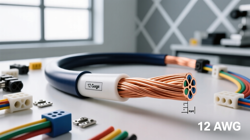
The Direct Answer: How Many Amps Can a 12 Gauge Wire Carry?
When diagnosing automotive electrical faults, the most common question technicians ask is: how many amps can a 12 gauge wire carry? In a standard 12V DC automotive environment, a single 12 AWG wire with SAE J1128 cross-linked insulation (GXL, TXL, or HDT) can safely carry 20 amps continuously in a high-temperature under-hood environment, and up to 25 amps in a cooler cabin or trunk environment.
However, ampacity is not a static number. It fluctuates based on ambient temperature, wire bundling, circuit length, and terminal integrity. If you are troubleshooting a melted harness, a repeatedly blown 20A ATO fuse, or a failing fuel pump, you must look beyond the basic AWG rating. This step-by-step troubleshooting flow will guide you through isolating 12 AWG circuit failures, verifying load limits, and executing proper repairs.
Phase 1: Symptom Isolation Decision Tree
Before unspooling new wire or swapping relays, identify the exact failure mode of your 12 AWG circuit. Use this diagnostic decision tree to pinpoint the root cause:
- Symptom: Wire insulation is melted, brittle, or tacky.
Cause: Continuous current exceeds 20A, or the wire is routed near exhaust manifolds exceeding the 125°C insulation rating.
Action: Proceed to Phase 2 to measure actual amperage and Phase 3 for environmental derating. - Symptom: 20A ATO/ATC fuse blows immediately upon ignition.
Cause: Dead short to chassis ground before the load, or a seized component (e.g., HVAC blower motor or fuel pump) drawing locked-rotor amperage.
Action: Disconnect the load. Test continuity from the load-side wire to chassis ground. If shorted, trace the harness for pinch points. - Symptom: Component underperforms (e.g., dim lights, slow wipers, fuel starvation at high RPM).
Cause: Severe voltage drop due to circuit length exceeding 12 feet on 12 AWG at 15A+, or high resistance at the crimp terminals.
Action: Proceed to Phase 4 for terminal analysis and Phase 5 for voltage drop testing. - Symptom: Relay chatters or clicks rapidly.
Cause: High inrush current (common in radiator cooling fans) causing momentary voltage drop, dropping the relay coil below its hold voltage.
Action: Verify 12 AWG is sufficient for the inrush spike; up-size to 10 AWG if the run exceeds 8 feet.
Phase 2: Load Verification & SAE Specifications
To accurately determine if your 12 AWG wire is overloaded, you must measure the actual current draw under load using an inductive DC clamp meter. Do not rely solely on the component's rated wattage, as aging motors draw significantly more amperage due to internal friction and brush wear.
Below is the definitive ampacity reference for 12 AWG wire, contrasting automotive standards with residential standards. For a deeper dive into wire gauge mathematics, refer to the Engineering ToolBox AWG Wire Gauge Chart.
| Standard / Environment | Insulation Type | Max Temp Rating | Continuous Ampacity | Burst / Inrush Limit |
|---|---|---|---|---|
| SAE J1128 (Under-Hood) | GXL / TXL (Cross-linked) | 125°C / 150°C | 20 Amps | 25 Amps (Max 5 sec) |
| SAE J1128 (Cabin/Trunk) | GXL / TXL (Cross-linked) | 125°C | 25 Amps | 32 Amps (Max 5 sec) |
| NEC Article 310 (Enclosed) | THHN / THWN (Copper) | 90°C | 20 Amps | N/A (Continuous Duty) |
| Chassis Ground Return | Bare / Ring Terminal | N/A | 41 Amps | 50 Amps (Max 2 sec) |
Note: The SAE J1128 Standard dictates that low-tension automotive wire must withstand specific heat, cold, and fluid exposure tests. Always use GXL or TXL for engine bay repairs, never PVC-based THHN.
Phase 3: Environmental Derating & Bundling Factors
A 12 AWG wire carrying 20A in free air will dissipate heat efficiently. However, automotive harnesses are rarely in free air. When troubleshooting a melted 12 AWG wire that is technically within the 20A limit, you must account for environmental derating.
The Bundling Penalty
When three or more current-carrying conductors are bundled together in a loom or conduit, the heat generated by each wire compounds. According to standard electrical derating curves, a bundle of 3 to 6 wires requires a 20% derating penalty. Therefore, a 12 AWG wire in a dense under-dash harness is only safe for 16 amps continuous. If your HVAC blower motor (often wired in 12 AWG Dark Green with a White tracer on GM trucks) pulls 18A on high speed, the bundled wires will slowly cook each other, leading to brittle insulation and eventual short circuits.
Ambient Heat Soak
If the 12 AWG wire is routed within 4 inches of the exhaust manifold or turbocharger downpipe, ambient temperatures can exceed 100°C before the wire even carries a load. In these zones, you must up-size to 10 AWG or use specialized fiberglass-braided high-temp sleeve wire to prevent insulation failure.
Phase 4: Terminal & Connector Integrity Check
Often, the 12 AWG wire itself is perfectly capable of carrying the load, but the failure occurs at the termination point. High resistance at the crimp generates localized heat, melting the connector housing long before the wire insulation fails.
- Inspect the Connector Housing: For high-current 12 AWG circuits (like fuel pumps or cooling fans), the industry standard is the Delphi (Aptiv) Metri-Pack 280 or Weather-Pack series. These terminals are rated for up to 30A, but only if the crimp is flawless.
- Verify the Crimp Profile: Pull back the silicone weather seal. Inspect the wire-to-terminal crimp. You should see the wire strands slightly flaring out at the front of the crimp barrel (the 'bellmouth'). If the crimp is loose, or if the insulation was crimped into the conductor wings, resistance will spike under load.
- Check for Terminal Fretting: Disconnect the connector and look at the male and female tangs. If you see white or green corrosion (fretting), the contact resistance has increased. A 15A load across a corroded Metri-Pack 280 terminal can generate enough heat to melt the nylon housing. Clean with electrical contact cleaner and apply dielectric grease, or replace the pigtail entirely.
Phase 5: Voltage Drop Testing & Corrective Action
If your 12 AWG wire is carrying less than 20A but the component is still failing, you are likely a victim of voltage drop. The longer the wire, the higher the resistance. A 12 AWG copper wire has a resistance of approximately 1.588 ohms per 1,000 feet.
Step-by-Step Voltage Drop Test
- Set your digital multimeter to DC Volts.
- Turn the circuit ON so current is flowing under load.
- Place the red multimeter probe on the positive battery terminal.
- Place the black multimeter probe on the component-side positive terminal (past the 12 AWG wire and any relays/fuses).
- Read the voltage. A healthy 12 AWG circuit should show a voltage drop of less than 0.2V (200mV). If you read 0.8V or higher, the wire is too long for the amperage, or there is a hidden corrosion point in a splice.
- Repeat the test on the ground side: Red probe to the component ground terminal, black probe to the negative battery post. Acceptable drop is less than 0.1V.
When to Up-Size to 10 AWG or 8 AWG
If your voltage drop test fails, or if your continuous load is measured between 20A and 30A, you must abandon the 12 AWG wire. Transition to 10 AWG GXL for loads up to 30A, or 8 AWG for loads up to 40A (such as aftermarket off-road light bars or high-amp winch solenoid feeds). When up-sizing, ensure you also upgrade the fuse holder (e.g., moving from an ATO blade fuse to a Maxi or MIDI fuse) and verify that the component's PCB pins or relay socket can physically accept the larger 10 AWG terminal crimp. Never force a 10 AWG wire into a Metri-Pack 150 connector; always step up to the 280 or 630 series cavity.