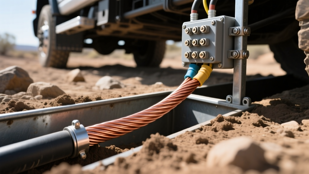
The Reality of Automotive 'Direct Burial' Environments
When automotive electricians and off-road fabricators discuss 'direct burial' wire, they are rarely talking about digging a trench in a residential backyard. In the context of heavy-duty trucks, agricultural equipment, and extreme off-road vehicles, a 'burial environment' refers to the enclosed, moisture-trapping cavities of a vehicle's frame rails, underbody skid plates, and trailer tongues. These areas act as subterranean vaults where water, road salt, mud, and debris accumulate and never fully dry out.
Standard PVC-insulated primary wire (such as SAE J1128 GPT) will quickly suffer from insulation degradation, copper oxidation, and capillary wicking in these environments. To ensure a reliable 30-amp continuous feed for electric trailer brakes, auxiliary fuel pumps, or heavy-duty winch solenoids, you must upgrade to 10 gauge wire direct burial specifications. This means utilizing cross-linked polyethylene (XLPE) or Underground Service Entrance (USE-2) rated conductors that can withstand continuous moisture immersion, extreme abrasion, and high thermal loads.
10 AWG Direct Burial Wire Specifications
Upgrading to a direct burial rated 10 AWG wire fundamentally changes the physical and chemical properties of your electrical run. According to guidelines established by the SAE J1128 standard and cross-referenced with NFPA 70 (NEC Article 339) for wet-location durability, XLPE and USE-2 wires undergo an electron-beam irradiation process. This cross-links the polymer chains, creating a thermoset insulation that will not melt, shrink back, or crack when exposed to high amperage heat or freezing mud.
| Parameter | Standard GPT (PVC) | Direct Burial (XLPE / USE-2) |
|---|---|---|
| Conductor Size (AWG) | 10 AWG (10,380 CM) | 10 AWG (10,380 CM) |
| Stranding | Standard Copper | Tinned Copper (Type III) |
| Insulation Material | Polyvinyl Chloride (PVC) | Cross-Linked Polyethylene (XLPE) |
| Max Temperature Rating | 105°C (221°F) | 125°C - 150°C (257°F - 302°F) |
| Moisture Resistance | Low (Capillary Wicking Risk) | Exceptional (Submersible) |
| Continuous Ampacity (Wet) | ~25 Amps (Derated) | 30 Amps (Maintains Rating) |
| Abrasion Resistance | Moderate | Extreme (Skid-Plate Safe) |
Step-by-Step Installation: 7-Way Trailer & Chassis Routing
Installing 10 gauge direct burial wire requires specific routing techniques to maximize the wire's inherent durability while protecting the vulnerable termination points. Below is the professional workflow for routing a 12V auxiliary and electric brake feed from a heavy-duty truck battery to the rear 7-way RV connector.
Step 1: Voltage Drop & Run Calculation
Before cutting your wire, calculate the voltage drop. A 10 AWG wire has a cross-sectional area of 10,380 Circular Mils (CM) and a resistance of approximately 1.018 ohms per 1,000 feet at 20°C. For a heavy-duty trailer pulling 30 amps across a 25-foot one-way run (50 feet total circuit length), the voltage drop is calculated as:
Voltage Drop = (2 x K x I x L) / CM
VD = (2 x 12.9 x 30 x 25) / 10,380 = 1.86 Volts
A 1.86V drop on a 12V system is roughly 15.5%, which is too high for sensitive electronic brake controllers. Solution: You must run the 10 AWG direct burial wire directly from a chassis-mounted auxiliary battery or a heavy-duty 80A relay located near the rear axle, keeping the actual 10 AWG run under 10 feet to maintain a sub-3% voltage drop.
Step 2: Frame Rail Routing and 'Burial' Protection
- Drilling the Frame: When passing the 10 AWG wire through boxed frame rails, use a stepped unibit to create clean, burr-free holes. Never route wire over sharp, punched factory metal.
- Grommet Installation: Insert heavy-duty EPDM rubber grommets into every frame hole. While XLPE insulation is highly abrasion-resistant, the constant harmonic vibration of a diesel chassis will eventually saw through any material resting against bare steel.
- The 'Burial' Zone: If routing the wire inside the boxed frame rail (the ultimate burial environment), do not use standard zip-ties. The wire will sit in the bottom of the rail, submerged in trapped water and road salt. Instead, use Adel Wiggins rubber-cushioned metal clamps secured with stainless steel hardware to suspend the wire in the upper third of the frame cavity, allowing water to drain beneath it.
Step 3: Marine-Grade Terminations
The weakest point of any direct burial installation is the termination. Moisture will seek out the gap between the wire strands and the terminal barrel, leading to galvanic corrosion and eventual open-circuit failure.
- Stripping: Use a precision wire stripper to remove exactly 7/16-inch of insulation. Do not nick the tinned copper strands, as this creates a focal point for corrosion.
- Crimping: Use a ratcheting indent-crimper designed for 10 AWG non-insulated terminals. The indent crimp creates a gas-tight, cold-weld seal that prevents moisture from entering the barrel.
- Sealing: Slide a 3:1 shrink ratio, dual-wall marine heat shrink tube over the connection. The inner wall contains a polyamide adhesive that melts and flows into the wire strands, creating a 100% waterproof seal. Heat evenly until the adhesive extrudes slightly from the ends.
Troubleshooting Wet-Environment Faults
Even with 10 gauge wire direct burial specifications, improper secondary sealing can lead to system failure. If your electric trailer brakes are pulsing or the auxiliary 12V feed is dropping out when driving through water, follow this diagnostic tree:
1. The 'Green Dust' Capillary Failure
Symptom: Voltage at the battery is 12.6V, but voltage at the 7-way connector (Pin 2 or Pin 4) drops below 9V under load. Inspection of the battery terminal reveals green copper sulfate powder.
Cause: Standard PVC wire allowed moisture to wick up the copper strands via capillary action, traveling from a compromised rear connection all the way to the battery.
Fix: Cut back the wire until you see bright, untarnished copper. Re-terminate using adhesive-lined heat shrink and apply a dielectric grease (not conductive carbon grease) to the exterior of the battery lug to displace ambient moisture.
2. Thermal Meltdown at the 7-Way Receptacle
Symptom: The plastic housing of the 7-way connector is melted or warped around the 12V auxiliary pin.
Cause: The factory 7-way connector uses cheap stamped brass pins that cannot handle 30 amps continuously, creating a high-resistance bottleneck. The 10 AWG wire stays cool, but the connector melts.
Fix: Bypass the factory connector. Install a heavy-duty, solid-brass pin replacement kit (such as the Pollak HD series). Ensure the set screws are torqued to 15 in-lbs and coated with marine-grade terminal grease to prevent oxidation.
Summary
Treating your heavy-duty truck or off-road rig's electrical system with the same respect as an underground utility line is the key to long-term reliability. By utilizing 10 gauge wire direct burial specifications—specifically tinned copper with XLPE or USE-2 insulation—you eliminate the risk of capillary wicking, insulation melting, and chassis-abrasion shorts. Combine this premium wire with gas-tight crimps, adhesive-lined heat shrink, and strategic frame-rail suspension, and your auxiliary power and trailer brake feeds will survive the harshest environments on earth.