Introduction: Sizing 10 Gauge Wire for High-Current Automotive Circuits
When designing or upgrading high-draw automotive electrical systems, selecting the correct conductor size is critical to preventing voltage drop, insulation meltdown, and catastrophic electrical fires. The 10 gauge wire standard occupies a vital middle ground in automotive wiring, bridging the gap between heavy-duty battery cables and standard 14-16 AWG accessory wiring. It is the industry standard for 30-amp to 40-amp continuous loads, making it the mandatory choice for electric cooling fans, aftermarket fuel pumps, winch control solenoids, and heavy-duty trailer brake controllers.
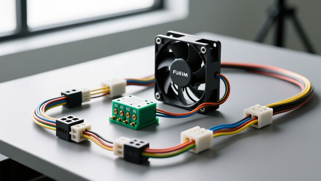
In this complete wiring diagram walkthrough, we will dissect a 40-amp electric cooling fan relay harness. We will trace the 10 gauge wire from the battery positive terminal through the primary overcurrent protection, into the switching relay, and out to the inductive load. This guide provides exact pin configurations, termination torque specifications, and SAE-compliant color codes to ensure your build meets professional motorsport and OEM standards.
The Critical Distinction: AWG vs. SAE 10 Gauge Specifications
Before routing any wire, automotive electricians must understand the discrepancy between standard American Wire Gauge (AWG) and Society of Automotive Engineers (SAE) sizing. While both are referred to as '10 gauge wire', SAE J1128 wire actually has a slightly smaller copper cross-sectional area than standard AWG. This occurs because SAE standards dictate individual strand diameters that result in less overall copper mass for the same nominal gauge size. If you are calculating voltage drop over a long run—such as routing 10 gauge wire to a rear-mounted transaxle cooler fan—you must use SAE resistance values to avoid undersizing the circuit.
| Specification Metric | Standard 10 AWG (B&S) | SAE J1128 (10 AWG GXL/TXL) |
|---|---|---|
| Cross-Sectional Area | 5.26 mm² | 5.07 mm² |
| Nominal Copper Strands | 105 strands (30 AWG each) | 73 strands (30 AWG each) |
| Resistance @ 20°C (per 1,000 ft) | 0.9989 Ohms | 1.018 Ohms |
| Max Ampacity (Engine Bay / 105°C) | 40 Amps | 35 Amps |
| Max Ampacity (Chassis / Bundled) | 30 Amps | 25 Amps |
Reference: Ampacity ratings derived from the SAE J1128 Low Tension Primary Cable Standard and adjusted for under-hood ambient temperature derating.
Complete Wiring Diagram Walkthrough: 40A Cooling Fan Circuit
The following walkthrough utilizes a standard Bosch-style ISO Mini Relay (5-pin, Type A configuration) to switch a dual-motor electric cooling fan drawing a combined 32 amps at peak stall, settling to a continuous 22 amps during operation. We will use SAE GXL 10 gauge wire for the high-current power feed and load circuits.
Node 1: Battery Positive to Primary Overcurrent Protection
Wire: 10 Gauge SAE GXL, Red Insulation.
Termination A (Battery): 5/16' (M8) closed-end ring terminal, adhesive-lined polyolefin heat shrink.
Termination B (Fuse Holder): Inline MAXI fuse holder with #10 screw stud.
Protection: 40A MAXI Blade Fuse.
The circuit begins at the battery positive post or a primary distribution busbar. The 10 gauge wire must be routed away from exhaust headers and steering shafts, secured every 12 inches with UV-resistant T-tape and split-loom corrugated tubing. According to Littelfuse Automotive High-Current Fuse guidelines, the overcurrent protection device must be located within 18 inches of the power source to protect the entire length of the 10 gauge wire against short-to-ground events. Use a ratcheting crimper to achieve an indent crimp on the ring terminal, followed by a heat gun application to melt the internal sealant adhesive, creating a waterproof barrier against battery acid corrosion.
Node 2: Fuse Output to Relay Power In (Pin 30)
Wire: 10 Gauge SAE GXL, Red Insulation.
Termination: Metri-Pack 280 series female terminal with secondary lock.
Leaving the 40A MAXI fuse, the 10 gauge wire connects to Pin 30 of the ISO Mini Relay. Pin 30 is the 'Common' power input. Because the under-hood environment is subject to severe vibration and moisture, bare spade terminals are strictly prohibited. The Metri-Pack 280 female terminal provides a high-normal-force connection that resists fretting corrosion. Ensure the terminal is fully seated until you hear an audible click, and engage the secondary TPA (Terminal Position Assurance) lock to prevent the wire from backing out of the relay socket during engine harmonic vibrations.
Node 3: Relay Load Out (Pin 87) to Electric Fan Motor
Wire: 10 Gauge SAE GXL, Red Insulation.
Termination A (Relay): Metri-Pack 280 series female terminal (Pin 87).
Termination B (Load): Deutsch DT 2-pin plug, Size 16 contacts.
Pin 87 is the Normally Open (NO) switched output. When the relay coil is energized, the internal contactor bridges Pin 30 to Pin 87, sending 12V+ down the 10 gauge wire to the cooling fan. At the fan shroud, terminate the wire into a Deutsch DT connector. The DT series is the gold standard for motorsport and heavy-duty truck applications, featuring a silicone rear grommet and a thermoplastic wedge lock that guarantees pin alignment and moisture ingress protection (IP68 rated). Do not use Pin 87a (Normally Closed) in this application; trim the unused wire flush and seal the cavity with a blanking plug to prevent dirt intrusion into the relay socket.
Node 4: The Ground Return Path (Crucial for 10 AWG Circuits)
Wire: 10 Gauge SAE GXL, Black Insulation.
Termination: 3/8' (M10) heavy-duty ring terminal.
A high-current circuit is only as reliable as its ground. The return path from the fan motor back to the chassis must also utilize 10 gauge wire to maintain a balanced circuit resistance. Locate a dedicated chassis ground stud or drill a new hole through bare, unpainted sheet metal. Use a star washer between the ring terminal and the chassis to bite through any microscopic oxidation, followed by a flat washer and an M10 flange nut. Torque the ground nut to 12 Nm (8.8 lb-ft). Coat the entire termination in dielectric grease or anti-corrosion compound to prevent galvanic corrosion, which will otherwise increase resistance and cause the fan motor to underperform.
Node 5: The Low-Current Control Circuit
While the 10 gauge wire handles the heavy lifting, the relay coil requires a control circuit.
Pin 86 (Coil +): 14 AWG Blue wire to a 12V Ignition-switched source (protected by a 5A ATO fuse).
Pin 85 (Coil -): 14 AWG Black wire to the output side of a thermal switch or ECU fan control driver.
When the thermal switch closes (or the ECU pulls the circuit to ground), the relay coil energizes, snapping the high-current 10 gauge circuit closed.
Troubleshooting & Voltage Drop Testing
Even with perfectly sized 10 gauge wire, poor terminations can introduce parasitic resistance. Never use a standard multimeter resistance (Ohms) setting to diagnose a high-current circuit; the meter's low test voltage will not reveal failing crimps under load. Instead, perform a Loaded Voltage Drop Test.
- Step 1: Turn the cooling fan on and allow it to reach full RPM (drawing maximum amperage).
- Step 2: Set your multimeter to DC Volts. Place the red probe on the battery positive post and the black probe on the relay Pin 30 terminal (piercing the wire seal or using a back-probe).
- Step 3: Read the voltage. A healthy 10 gauge wire and crimp connection should show a voltage drop of less than 0.10V.
- Step 4: Move the black probe to the relay Pin 87 terminal. The drop across the internal relay contactor should be less than 0.15V.
- Step 5: Test the ground side by placing the red probe on the fan motor casing and the black probe on the battery negative post. The drop across the 10 gauge ground wire and chassis stud should be less than 0.10V.
If any segment exceeds 0.2V under load, you have identified a high-resistance fault. This is typically caused by a non-ratcheting crimp tool failing to compress the copper strands adequately, or the use of cheap, non-tinned copper terminals that have oxidized internally. Cut the faulty termination back to bare, bright copper, and re-crimp using a proper indent-style tool.
Authoritative References & Standards
Designing safe, reliable automotive electrical systems requires adherence to established engineering standards. The specifications and methodologies detailed in this walkthrough are governed by the following authorities:
- SAE J1128 Low Tension Primary Cable Standard - Defines the physical dimensions, insulation materials (GXL, TXL, SXL), and thermal ratings for automotive primary wire.
- NFPA 70 National Electrical Code (NEC) Article 310 - Provides baseline ampacity tables and temperature derating factors applicable to bundled DC wiring harnesses.
- Littelfuse Automotive High-Current Fuses - Outlines time-current characteristics and interrupting ratings for MAXI and MEGA fuses used in 10 AWG power feeds.
By strictly adhering to these 10 gauge wire routing protocols, termination standards, and diagnostic procedures, you ensure that high-draw automotive accessories operate reliably under the most extreme thermal and vibrational conditions.