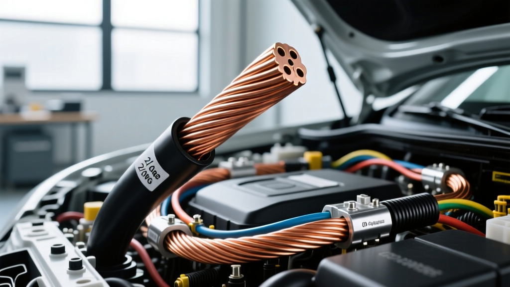
Introduction to 00 Gauge (2/0 AWG) in Modern Automotive Systems
In the realm of high-performance automotive electrical systems, electric vehicle (EV) conversions, and heavy-duty off-grid builds, 00 gauge wire—universally recognized in engineering circles as 2/0 AWG or 'double-aught'—represents the critical threshold for high-amperage direct current (DC) power transmission. Whether you are routing main battery cables for a 400V EV drive unit, upgrading the charging circuit for a 250-amp alternator in an overland expedition vehicle, or wiring a 12,000-pound hydraulic winch, understanding the precise physical and electrical characteristics of 2/0 AWG is non-negotiable. Misjudging the ampacity or voltage drop of this massive conductor can lead to catastrophic thermal events, insulation meltdown, or severe voltage starvation at the load.
The nomenclature surrounding this wire size often causes confusion among novice builders. The '00' designation is a colloquialism; the correct American Wire Gauge (AWG) nomenclature is 2/0, which mathematically translates to a cross-sectional area of 133,100 circular mils (kcmil). In metric terms, 2/0 AWG is most frequently cross-referenced with 70mm² cable in ISO and European automotive standards, though subtle differences in stranding and exact cross-sectional area exist between the two standards.
Physical Dimensions and SAE J1128 Compliance
When sourcing 00 gauge wire for automotive applications, it is imperative to verify that the cable meets SAE J1128 standards for Low Tension Primary Cable or specific high-voltage EV standards if used in electrified powertrains. Standard 2/0 AWG battery cable typically features a highly flexible stranding configuration, often utilizing 30 AWG or 34 AWG bare copper strands bundled together to withstand the constant vibration and thermal cycling inherent to vehicle chassis environments.
| Specification | 2/0 AWG (00 Gauge) Metric / Imperial |
|---|---|
| Nominal Cross-Sectional Area | 67.43 mm² (133.1 kcmil) |
| Overall Diameter (OD) with Insulation | 0.520 inches (13.2 mm) typical |
| Conductor Diameter (Bare) | 0.3648 inches (9.266 mm) |
| DC Resistance @ 20°C (68°F) | 0.1563 Ohms per 1,000 feet |
| Weight (Copper Only) | 403 lbs per 1,000 feet |
| Standard Stranding (High Flex) | 624 strands of 30 AWG |
Metric Equivalencies: 2/0 AWG vs. 70mm²
While often used interchangeably in custom EV swaps (such as installing a Tesla Large Drive Unit into a classic chassis), 2/0 AWG (67.43 mm²) and ISO 70mm² are not perfectly identical. The 70mm² metric cable possesses approximately 3.8% more copper cross-sectional area. In high-draw scenarios, such as pulling 300 amps from a lithium iron phosphate (LiFePO4) house bank to a 3000W inverter, this slight difference can marginally affect thermal performance. However, for 95% of automotive 12V/24V applications, the termination hardware (lugs and busbars) is designed to accept both interchangeably, provided the crimp die is matched to the specific wire's outer diameter.
Ampacity Ratings and Thermal Derating Factors
Ampacity—the maximum amount of electric current a conductor can carry before sustaining thermal degradation—is highly dependent on insulation type, ambient temperature, and whether the wire is routed in free air or bundled in a conduit. Relying on generic 'internet charts' for 00 gauge wire ampacity is a primary cause of electrical fires in custom vehicles. According to the National Electrical Code (NFPA 70) and specialized automotive engineering guidelines, the baseline ampacity fluctuates significantly based on the insulation jacket.
| Insulation Type | Max Temp Rating | Chassis Wiring Ampacity (Single Cable, Free Air) | Common Automotive Use Case |
|---|---|---|---|
| PVC (Standard Battery Cable) | 105°C | 175 Amps | 12V Starter circuits, Winch wiring |
| XLPE (Cross-Linked Polyethylene) | 125°C | 210 Amps | EV Battery interconnects, Alternator upgrades |
| Silicone Rubber | 150°C | 225 Amps | High-heat engine bays, Racing applications |
| PTFE / Teflon | 200°C | 260 Amps | Aerospace, Extreme motorsport environments |
Expert Derating Note: If your 2/0 AWG cable is routed through a conduit, bundled with other current-carrying conductors, or exposed to under-hood ambient temperatures exceeding 50°C (122°F), you must apply a thermal derating factor. For example, routing standard 105°C PVC 2/0 wire near a turbocharger exhaust manifold where ambient temps reach 85°C requires derating the 175A capacity by roughly 41%, reducing its safe continuous limit to just 103 amps. In these environments, XLPE or Silicone-jacketed 00 gauge wire is mandatory.
High-Amp Applications: EV Swaps and Alternator Upgrades
EV Battery Pack Interconnects and Inverter Routing
In 400V to 800V EV architectures, 00 gauge wire is the standard for module-to-module and pack-to-inverter interconnects. High-voltage 2/0 AWG cable is universally jacketed in orange XLPE to denote lethal DC voltage. When terminating these cables into modern inverters (such as the Cascadia Motion or BorgWarner units), builders utilize specialized shielded connectors like the Amphenol SurLok Plus (5.7mm or 8.0mm variants). The SurLok Plus features an integrated High Voltage Interlock Loop (HVIL) and requires a precise radial hex crimp on the 2/0 AWG wire to ensure the internal contact fingers mate perfectly without inducing localized resistance.
High-Output Alternator and Overland Dual-Battery Systems
For expedition vehicles (e.g., 200-series Land Cruisers or Sprinter vans) running 200A to 320A aftermarket alternators (like those from Mechman or Power Bastards), the factory 4 AWG or 2 AWG alternator charge wire is entirely inadequate. Upgrading to 00 gauge wire from the alternator B+ terminal to the primary busbar or battery isolation manager (BIM) ensures that the massive charging current reaches the house bank without suffering a 1.5V drop, which would prematurely trigger the alternator's internal voltage regulator to taper output. Standardizing on red XLPE 2/0 AWG for the positive and black for the negative return path maintains SAE color-code compliance while maximizing thermal headroom.
Termination Physics: Crimping vs. Soldering 2/0 AWG
A persistent myth in amateur automotive wiring is that soldering heavy-gauge wire provides a superior connection. In the context of 00 gauge wire, soldering is strictly prohibited for high-vibration, high-amperage chassis connections. Solder does not possess the same tensile strength or fatigue resistance as copper. Under the constant vibration of a vehicle chassis, a soldered 2/0 AWG joint will work-harden and eventually fracture, leading to high-resistance arcing. Furthermore, the wicking action of molten solder into the 624 strands of a 2/0 cable creates a rigid, inflexible section right behind the lug barrel, acting as a stress riser that guarantees eventual strand failure.
Tooling and Lug Selection (M8/M10, 3/8', 1/2')
Proper termination of 2/0 AWG requires a cold-weld hex crimp or an indent crimp using a calibrated hydraulic or pneumatic tool (such as the Klauke or Greenlee 12-ton hydraulic crimpers). The copper lug must be rated for the specific stranding (e.g., fine-strand vs. coarse-strand).
- Hex Crimping: Compresses the barrel evenly into a hexagonal shape, aligning perfectly with standard busbar studs and providing maximum pull-out strength.
- Sealing: After crimping, the barrel must be sealed using dual-wall, adhesive-lined polyolefin heat shrink (typically 3/4' or 1' diameter). The inner thermoplastic adhesive melts and flows into the copper strands, creating a hermetic seal that prevents galvanic corrosion and moisture ingress—a critical failure point in marine and off-road environments.
- Torque Specs: When bolting a 2/0 AWG M10 (3/8') ring terminal to a copper busbar or battery post, the torque specification is generally 25-30 Nm (18-22 ft-lbs). Under-torquing causes micro-arcing; over-torquing yields the copper lug, reducing the contact surface area and increasing resistance.
Voltage Drop Calculations for 12V and 48V Systems
Voltage drop is the true enemy of high-amperage DC systems. Using data derived from standard copper wire sizing calculators, we can map the exact voltage loss over varying distances. Remember that total circuit length must account for both the positive and negative return paths (i.e., a 10-foot physical run equals 20 feet of total wire length for calculation purposes).
| System Voltage | Current Draw | Total Wire Length (Pos + Neg) | Voltage Drop (2/0 AWG) | Percentage Drop |
|---|---|---|---|---|
| 12V (Winch) | 400 Amps (Peak) | 10 Feet | 0.625 Volts | 5.2% (Acceptable for intermittent peak) |
| 12V (Alternator) | 200 Amps (Cont.) | 20 Feet | 0.625 Volts | 5.2% (Marginal, consider parallel runs) |
| 48V (EV / Solar) | 150 Amps (Cont.) | 20 Feet | 0.468 Volts | 0.97% (Excellent) |
| 400V (EV Pack) | 250 Amps (Cont.) | 12 Feet | 0.468 Volts | 0.11% (Negligible) |
For continuous 12V loads exceeding 150 amps over distances greater than 8 feet, 00 gauge wire begins to reach the 3% voltage drop limit recommended for sensitive automotive electronics. In such scenarios (like running a 3000W 12V inverter in a long-wheelbase van), builders must either step up to 4/0 AWG, parallel two runs of 2/0 AWG, or transition to a 24V/48V system architecture to reduce amperage.
Expert Troubleshooting and Real-World Failure Modes
When diagnosing faults in high-amp circuits utilizing 00 gauge wire, thermal imaging (FLIR) is your most valuable diagnostic tool. A healthy 2/0 AWG crimp operating at 150 amps should not exhibit a temperature delta greater than 5°C above ambient. Common Failure Modes:
- The 'False Crimp': Using an undersized die (e.g., a 1 AWG die on a 2/0 lug) or failing to strip the insulation back far enough, resulting in the crimp die biting into the wire jacket rather than the copper. This creates a high-resistance bottleneck that will melt the lug barrel under load.
- Galvanic Corrosion at Busbars: Connecting tinned 2/0 AWG lugs directly to bare aluminum busbars without bi-metallic washers or dielectric grease. The dissimilar metals create a galvanic cell in the presence of humidity, rapidly increasing contact resistance and causing localized heating.
- Strand Fatigue: Routing 00 gauge wire with a bend radius tighter than 4x its outer diameter (less than 2 inches). This over-stresses the outer strands while compressing the inner strands, fundamentally altering the wire's resistance profile and leading to internal hot-spots that are invisible from the outside.
By respecting the physical limitations, thermal derating curves, and termination physics of 00 gauge wire, automotive electricians and EV conversion specialists can build power distribution networks that are not only capable of handling extreme amperage but are engineered to survive the brutal realities of the automotive environment.