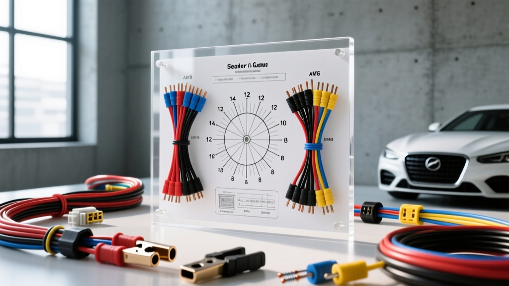
The Flaw in Standard Speaker Wire Charts
Most generic speaker wire gauge charts found online are designed for home theater applications, assuming static 8-ohm loads, short 10-foot runs, and climate-controlled environments. In the automotive sector, these assumptions fail catastrophically. Car audio systems regularly subject wiring to 1-ohm stable monoblock amplifiers pushing over 100 amps of continuous current, 14.4V alternator ripple, extreme temperature fluctuations, and high-vibration door hinge transitions. Choosing the correct American Wire Gauge (AWG) for your car audio system requires an advanced understanding of impedance, damping factor, and material science.
Advanced Speaker Wire Gauge Chart (Impedance & Run Length)
The following chart calculates maximum one-way run lengths based on a strict 5% voltage drop threshold, which is the industry standard for maintaining acoustic integrity and amplifier stability. This data assumes 100% Oxygen-Free Copper (OFC) at 20°C. If you are using Copper-Clad Aluminum (CCA), you must step up one full AWG size to compensate for the 39% higher resistivity of aluminum.
| AWG Size | Cross-Section (mm²) | Resistance (Ω/ft) | Max Run @ 4Ω (5% Drop) | Max Run @ 2Ω (5% Drop) | Max Run @ 1Ω (5% Drop) |
|---|---|---|---|---|---|
| 18 AWG | 0.82 | 0.00639 | 15 ft | 7 ft | Not Recommended |
| 16 AWG | 1.31 | 0.00402 | 24 ft | 12 ft | 6 ft |
| 14 AWG | 2.08 | 0.00253 | 39 ft | 19 ft | 9 ft |
| 12 AWG | 3.31 | 0.00159 | 62 ft | 31 ft | 15 ft |
| 10 AWG | 5.26 | 0.00100 | 99 ft | 49 ft | 24 ft |
| 8 AWG | 8.37 | 0.00063 | 157 ft | 78 ft | 39 ft |
Note: For subwoofer applications utilizing 12 AWG or thicker wire, always utilize ring terminals crimped with a pneumatic or heavy-duty ratcheting crimper to minimize transition resistance at the amplifier block.
Damping Factor: The Hidden Metric of Bass Control
Advanced installers do not just size wire to prevent voltage drop; they size wire to preserve the amplifier's damping factor (DF). Damping factor is the amplifier's ability to control the mechanical movement of the speaker cone, particularly the back-EMF generated by a subwoofer's voice coil during transient stops. A loss of damping factor results in 'muddy' or 'boomy' bass response.
The Damping Factor Formula
The effective damping factor is calculated as:
DF = Load Impedance / (Amplifier Output Impedance + Wire Resistance)
Consider a high-end amplifier like the JL Audio HD1200/1, which boasts an output impedance of roughly 0.02 ohms. If you run 16 AWG wire for a 15-foot run to a dual 2-ohm subwoofer configuration (wired in parallel for a 1-ohm load), the total round-trip wire resistance is approximately 0.12 ohms.
- Ideal DF (No wire): 1.0 / 0.02 = 50
- Actual DF (With 16 AWG): 1.0 / (0.02 + 0.12) = 7.14
By simply upgrading to 8 AWG speaker wire for this high-current subwoofer run, the wire resistance drops to 0.018 ohms, raising the effective damping factor back to 26.3. This is why referencing a comprehensive speaker wire gauge chart that accounts for sub-2-ohm loads is critical for competition-level SPL and SQ (Sound Quality) builds.
Material Science: OFC vs. CCA in Automotive Environments
The automotive environment is hostile to electrical connections. While SAE J1128 standards primarily dictate the thermal and abrasion requirements for low-tension primary cables in engine bays, the principles of material degradation apply directly to speaker wire routed through door sills, under carpets, and near HVAC drains.
The Galvanic Corrosion Threat
Copper-Clad Aluminum (CCA) wire is manufactured by bonding a thin layer of copper over an aluminum core. While it is cheaper and lighter, it poses severe risks in car audio:
- Oxidation at Crimp Joints: When CCA is cut, the aluminum core is exposed to ambient humidity. Aluminum oxide forms rapidly, creating a high-resistance dielectric barrier at your amplifier's set-screw terminals.
- Galvanic Corrosion: If CCA wire comes into contact with dissimilar metals (like the nickel-plated brass terminals found on most aftermarket amplifiers) in the presence of moisture (e.g., a wet floorboard from a clogged AC drain), it creates a galvanic cell. The aluminum acts as an anode and corrodes away, eventually snapping under the vibration of the vehicle chassis.
For any permanent, high-fidelity installation, 99.9% pure Oxygen-Free Copper (OFC) is mandatory. For authoritative testing on conductivity and signal loss, resources like Audioholics provide extensive teardowns proving the long-term degradation of CCA in varying climates.
Stranding, Door Boots, and Vibration Fatigue
Wire gauge is only one dimension of the specification. The stranding count dictates the wire's flexibility and fatigue life. In automotive applications, speaker wires must pass through the rubber door boot (the conduit between the A-pillar and the front doors). Every time the door is opened and closed, the wire undergoes severe mechanical flexing.
Standard 16 AWG wire with 26 strands will work-harden and fracture within 12 to 18 months of daily use. For door speakers, you must specify high-strand count (HSC) or extra-high-strand count wire. For example, a premium 16 AWG automotive speaker wire should feature upwards of 1,100 individual 0.1mm strands. This tinsel-like construction distributes the mechanical stress, preventing copper fatigue and subsequent open-circuit failures.
OEM High-Level Integration and Polarity Mapping
When integrating aftermarket amplifiers via high-level inputs into modern factory harnesses (such as the FCA 9-speaker Alpine system or Ford B&O systems), you are often tapping into 18 AWG or 20 AWG OEM speaker wires. While these OEM wires are sufficient for the factory 20W RMS head unit, they become a choke point when feeding a high-impedance DSP (Digital Signal Processor) summing network.
Common OEM Speaker Wire Color Codes (Ford Example)
- Front Left (+/-): White / White with Black Stripe
- Front Right (+/-): White with Red Stripe / White with Blue Stripe
- Rear Left (+/-): White with Green Stripe / White with Brown Stripe
- Rear Right (+/-): White with Violet Stripe / White with Yellow Stripe
Expert Tip: Always verify polarity with an oscilloscope or a dedicated digital phase tester (like the Sencore SG80) before soldering your 14 AWG OFC pigtails to the OEM harness. Modern Class D factory amplifiers often utilize floating grounds or differential balanced outputs; grounding a high-level negative wire to the vehicle chassis will instantly short and destroy the OEM amplifier's output stage.
High-Frequency Attenuation and the Skin Effect
For component tweeters and high-frequency compression drivers, the inductance and capacitance of the speaker cable can act as an unintended low-pass filter. While the 'skin effect' (where high frequencies travel only on the outer surface of the conductor) is largely negligible at audio frequencies (20Hz - 20kHz) compared to RF applications, the proximity effect and dielectric losses in cheap PVC insulation can cause micro-attenuation in the 10kHz+ range.
For audiophile-grade SQ builds, routing 14 AWG OFC wire with a Tefzel (PTFE) or high-density polyethylene (HDPE) dielectric jacket ensures that the capacitance per foot remains exceptionally low, preserving the transient attack of cymbals and high-hats without introducing phase shift at the crossover network.
Summary Checklist for Automotive Sizing
- Subwoofers (1Ω - 2Ω): Minimum 8 AWG to 4 AWG OFC, high-strand, ring terminals.
- Mid-Bass/Midrange (4Ω): 12 AWG to 14 AWG OFC, spade or bare wire into set-screws.
- Tweeters/Horns (8Ω): 16 AWG OFC, soldered and heat-shrunk at crossover networks.
- Door Boot Runs: Mandatory extra-high-strand count to prevent fatigue snapping.
By treating your speaker wire as a critical component of the electrical circuit rather than an afterthought, you ensure that the voltage generated at the amplifier's output stage is exactly what arrives at the voice coil, maximizing both SPL output and sonic accuracy. For further reading on vehicle-specific electrical upgrades and alternator matching, consult the technical whitepapers provided by Crutchfield's Car Audio Engineering Team.