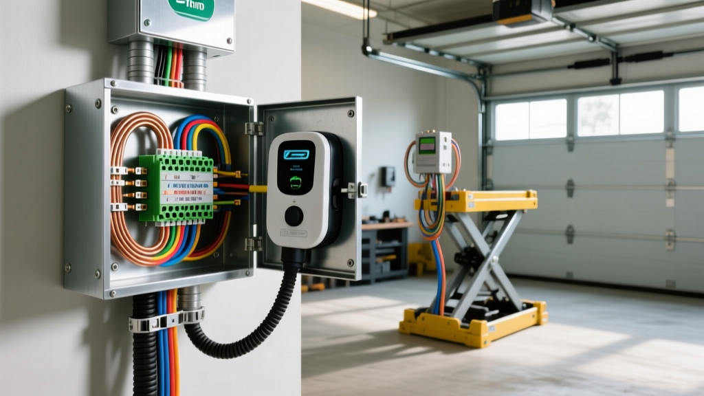
The Ultimate Automotive Garage: 100A Subpanel Walkthrough
Upgrading your home garage or automotive shop to handle professional-grade equipment requires serious electrical infrastructure. Whether you are installing a Level 2 EV charger for your daily driver, a 2-post asymmetric lift for engine pulls, or a high-duty-cycle MIG welder for chassis fabrication, your main residential panel often lacks the capacity and physical breaker spaces to support these heavy loads. This is where a dedicated subpanel becomes mandatory. However, determining the correct wire gauge for 100 amp subpanel configurations is a common stumbling block for automotive enthusiasts transitioning into garage facility management.
In this complete wiring diagram walkthrough, we will bridge the gap between automotive electrical theory and the NFPA 70 National Electrical Code (NEC) requirements. We will cover feed wire sizing, conduit fill, branch circuit calculations for specific automotive tools, and the critical torque specifications that prevent catastrophic lug failures.
Phase 1: Sizing the Main Feed Wire
The foundation of your garage build relies on the feeder cables running from your main service panel to the subpanel. According to Mike Holt's NEC Technical References and NEC Article 310.16, wire ampacity is determined by the lowest temperature rating of any connected lug, device, or conductor. Most standard 100A subpanels and breakers are rated for 75°C. Therefore, we must use the 75°C column for our gauge calculations, regardless of the 90°C rating on the wire jacket.
Copper vs. Aluminum Feeders
- Copper (THHN/THWN-2): Requires 2 AWG copper wire. At 75°C, 2 AWG copper is rated for 115 amps, safely exceeding the 100A breaker limit and providing a buffer for voltage drop over longer distances.
- Aluminum (XHHW-2): Requires 1/0 AWG aluminum wire. At 75°C, 1/0 AWG is rated for exactly 100 amps. While aluminum is more cost-effective for long trench runs to detached garages, it requires larger conduit and specialized anti-oxidant paste (like Noalox) at the terminations to prevent galvanic corrosion and arcing.
Phase 2: Complete Wiring Diagram Walkthrough
Visualizing the path of current is essential for troubleshooting and passing municipal inspections. Below is the step-by-step diagram walkthrough for a standard 240V/120V split-phase garage subpanel setup.
Step 1: Main Panel Termination
Install a 100A double-pole breaker in your main service panel. Connect the Black (Hot 1) and Red (Hot 2) 2 AWG wires to the breaker lugs. Connect the White (Neutral) to the main neutral busbar, and the Green/Bare (Ground) to the main equipment grounding busbar. Note: In the main panel, neutral and ground are bonded. In the subpanel, they must remain strictly isolated.
Step 2: Conduit Routing and Fill
For a 4-wire feeder setup (2 Hots, 1 Neutral, 1 Ground), you are pulling four 2 AWG THHN wires plus a 6 AWG green ground wire. According to NEC Chapter 9 Table 1, conduit fill must not exceed 40% for three or more wires. A 1.25-inch Schedule 80 PVC conduit is the minimum requirement, but stepping up to 1.5-inch PVC is highly recommended to reduce pulling friction and heat buildup.
Step 3: Subpanel Lug Termination
At the 100A main-lug subpanel, land the Black and Red wires on the main hot lugs. Land the White wire on the isolated neutral busbar. Land the Green wire on the separate equipment grounding busbar. Ensure the bonding screw or strap inside the subpanel is removed to prevent neutral current from traveling back along the ground wire, which can cause electromagnetic interference (EMI) with sensitive automotive diagnostic scanners and ECU flashing tools.
Phase 3: Automotive Branch Circuit Sizing
Once the subpanel is energized, you must distribute power to your specific automotive equipment. Automotive tools have unique load profiles, particularly regarding inrush current and duty cycles.
| Automotive Equipment | Breaker Size | Wire Gauge (Copper) | NEC Article / Rule |
|---|---|---|---|
| Level 2 EV Charger (e.g., 48A continuous) | 60A Double-Pole | 4 AWG THHN | 210.20(A) Continuous Loads (125% rule) |
| 2-Post Asymmetric Lift (3HP Motor) | 30A Double-Pole | 10 AWG THHN | 430.52 Motor Starting Current |
| MIG Welder (e.g., 250A output) | 50A Double-Pole | 6 AWG THHN | 630.11 Welder Duty Cycle Calculation |
| Plasma Cutter / Air Compressor | 30A / 20A | 10 AWG / 12 AWG | Standard Receptacle Sizing |
EV Charger Sizing Deep Dive
According to the U.S. Department of Energy EV Charging Guidelines, Level 2 chargers are considered continuous loads because they operate for 3 hours or more. If you install a charger capable of delivering 48 amps to the vehicle, the NEC requires the circuit to be rated for 125% of the continuous load (48 x 1.25 = 60 amps). Therefore, you must use a 60A breaker and 4 AWG copper wire. Using 6 AWG on a 60A breaker is a severe fire hazard and will fail inspection.
Welder Duty Cycle Considerations
Automotive welders rarely pull their maximum primary amperage continuously. NEC Article 630 allows you to size the wire and breaker based on the welder's duty cycle rather than its absolute maximum draw. A typical 250-class MIG welder drawing 50A at a 40% duty cycle can often be wired with 6 AWG copper and a 50A breaker, preventing nuisance tripping while maintaining safety.
Phase 4: Grounding Protocols for Detached Garages
If your automotive shop is in a detached building, NEC 250.32 dictates specific grounding rules. You must run a dedicated Equipment Grounding Conductor (EGC) with your feeder wires. For a 100A subpanel, the EGC must be a minimum of 6 AWG copper or 4 AWG aluminum.
Additionally, detached structures require a supplemental grounding electrode system (typically two 5/8-inch copper-clad ground rods driven 6 feet apart and bonded with 6 AWG bare copper). This protects your expensive automotive diagnostic equipment and EV chargers from lightning strikes and transient voltage surges originating from the utility grid.
Phase 5: Torque Specifications and Failure Modes
Automotive mechanics are accustomed to torquing head bolts and lug nuts to precise specifications, yet frequently overlook electrical torque specs. A loose lug on a 100A subpanel feed creates high resistance, generating massive heat that melts insulation and causes arcing faults.
- Stripping Length: Strip exactly 3/4 inch of insulation from 2 AWG THHN. Exposed copper outside the lug barrel is a shock hazard and a short-circuit risk.
- Torque Specs: Most 100A rated Square D and Eaton lugs require between 45 and 55 inch-pounds of torque for 2 AWG wire. Always verify the torque spec printed on the subpanel label.
- Tooling: Use a calibrated dial torque screwdriver or a digital torque adapter. Do not guess using a standard nut driver.
Common Failure Modes in Garage Subpanels
- Neutral-Ground Bonding in Subpanel: Failing to remove the bonding screw causes neutral return current to flow through the conduit and grounding rods, creating stray voltage that can shock you when touching the vehicle chassis and the lift simultaneously.
- Undersized Feed for Distance: If your detached garage is over 150 feet from the main panel, voltage drop becomes critical. You must upsize the feeder to 1/0 AWG Copper or 2/0 AWG Aluminum to keep voltage drop below 3%, ensuring your EV charger doesn't abort charging cycles due to low-voltage errors.
- Aluminum Oxidation: Failing to apply anti-oxidant compound to aluminum feeders results in increased resistance over time, eventually leading to thermal meltdown at the main breaker lugs.
By treating your garage electrical infrastructure with the same precision and respect as a high-performance engine build, you ensure a safe, reliable, and code-compliant workspace capable of handling the most demanding automotive tools and EV charging requirements.