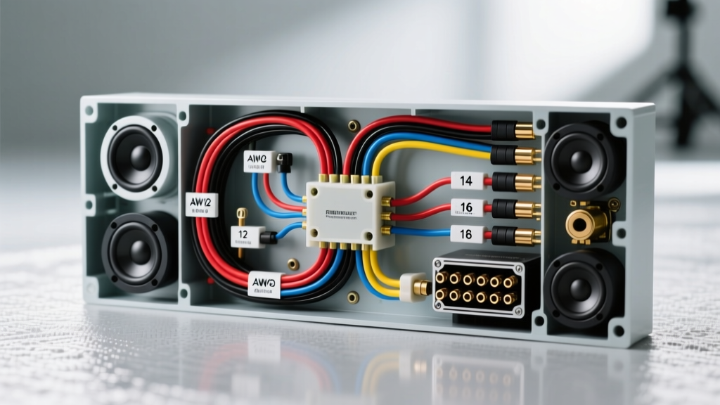
Decoding the Car Audio Signal Path
When installing a mobile audio system, reading a wiring diagram is only the first step. Translating that schematic into physical reality requires a deep understanding of current flow, impedance, and resistance. This automotive speaker wire gauge guide walks you through a standard car audio wiring diagram, segment by segment, to explain exactly where and why specific American Wire Gauge (AWG) sizes must be deployed. Unlike home audio, automotive environments present severe space constraints, extreme temperature fluctuations, and complex 12V DC electrical noise. Choosing the correct gauge is not just about preventing melted wires; it is about preserving the amplifier's damping factor and ensuring accurate transient response at the voice coil.
Segment 1: Head Unit to Amplifier (Signal Level)
Tracing the diagram from the source unit, the first segment involves the signal transfer. If your diagram shows low-level RCA connections, you are dealing with shielded coaxial cables, not standard speaker wire. However, if your schematic depicts a high-level (speaker-level) input harness connecting the factory head unit to an aftermarket amplifier's high-level input pins, wire gauge becomes relevant. Factory wiring is typically 20 to 22 AWG. When tapping into this for an active line output converter (LOC) or high-level amp inputs, use 18 AWG oxygen-free copper (OFC) wire. This provides a robust mechanical connection when using solder-seal heat shrink connectors without overloading the delicate factory head unit output transistors.
Segment 2: Amplifier to Passive Crossover Network
Moving down the signal chain, the diagram shows the amplified output leaving the Class D or Class AB amplifier terminals. If your system utilizes outboard passive crossovers, the wire run from the amp to the crossover box must handle the full, unfiltered RMS wattage of the channel. For a standard 4-ohm component set driven by 75W RMS per channel, 14 AWG OFC wire is mandatory. Using 16 AWG here will introduce unnecessary series resistance, which alters the crossover's frequency cutoff points and degrades the Q-factor of the passive filters.
Segment 3: Crossover to Speaker Voice Coil
The final segment connects the crossover outputs (or the amplifier directly, in an active setup) to the speaker terminals inside the door panel or kick panel. This is where physical routing constraints often tempt installers to use thinner wires. Do not compromise. The wire must pass through the door jamb rubber boot, a notorious choke point. According to the Consumer Technology Association (CTA) mobile electronics installation standards, maintaining consistent gauge from the amp to the speaker terminals is critical for preserving the amplifier's damping factor, which controls speaker cone excursion after the signal stops.
The Automotive Speaker Wire Gauge Guide Chart
Selecting the correct gauge depends on three variables: the continuous RMS power output, the nominal impedance of the speaker load, and the physical length of the wire run. The chart below assumes the use of true Oxygen-Free Copper (OFC). If you are using Copper-Clad Aluminum (CCA), you must step up one full AWG size (e.g., use 14 AWG CCA instead of 16 AWG OFC) to compensate for aluminum's 30% higher electrical resistance.
| AWG Size | Max RMS Power (4-Ohm) | Max RMS Power (2-Ohm) | Max Run Length (OFC) | Typical Application |
|---|---|---|---|---|
| 18 AWG | 50 Watts | Not Recommended | 12 Feet | Low-power rear fill, tweeters |
| 16 AWG | 100 Watts | 50 Watts | 15 Feet | Standard 6.5" coaxials, door speakers |
| 14 AWG | 150 Watts | 100 Watts | 20 Feet | Component sets, high-power midbass |
| 12 AWG | 250+ Watts | 200 Watts | 25+ Feet | Subwoofers, high-SPL midrange |
EIA/CEA Standard Wiring Color Codes
When reading a factory wiring diagram or interfacing with an aftermarket harness, adherence to the EIA/CEA-315 standard is universal across the mobile electronics industry. Misinterpreting these colors during the diagram walkthrough will result in out-of-phase speakers, destroying stereo imaging and bass response.
- Front Left: White (Positive) / White with Black Stripe (Negative)
- Front Right: Gray (Positive) / Gray with Black Stripe (Negative)
- Rear Left: Green (Positive) / Green with Black Stripe (Negative)
- Rear Right: Purple (Positive) / Purple with Black Stripe (Negative)
Expert Note: The 'black stripe' universally denotes the negative return path in DC automotive audio applications. Never use the vehicle's chassis ground for speaker returns; modern amplifiers utilize Bridge-Tied Load (BTL) output stages, and grounding a speaker wire will instantly short the amplifier's output MOSFETs.
Physical Routing: Diagram to Reality
A schematic shows a clean, direct line from Point A to Point B. The physical vehicle requires navigating the A-pillar, the floor harness conduit, and the door hinge boot. When pulling 14 or 12 AWG wire into a door panel, use a dedicated wire fish tape and apply a dielectric silicone lubricant to the wire jacket to prevent tearing the factory rubber weather seal. Always route speaker wires on the opposite side of the vehicle's interior from the 12V power and ground cables to prevent electromagnetic interference (EMI), which manifests as alternator whine. Furthermore, maintain a strict minimum 6-inch separation from any yellow-jacketed SRS (airbag) wiring to ensure safety compliance and prevent accidental deployment triggers during installation.
For terminations at the speaker basket, avoid the use of 'T-Tap' scotch locks or crimp-only butt connectors, which are highly susceptible to vibration-induced failure and moisture corrosion inside the door cavity. As highlighted in Crutchfield's wiring archives, the gold standard for automotive speaker termination is the solder-seal heat shrink connector, or ideally, soldering the wire directly to a spade terminal that mates with the speaker's push-tab. For high-end installations, utilizing marine-grade adhesive-lined heat shrink (such as 3M FP-301) over the solder joint creates a waterproof seal that prevents copper oxidation from the humid environment inside a car door.
Advanced Troubleshooting: When the Gauge is Wrong
If you have followed the wiring diagram but are experiencing audio anomalies, the wire gauge or routing may be the culprit. Use this decision tree to diagnose gauge-related failures:
- Symptom: Bass sounds 'muddy' or lacks impact at high volumes.
- Cause: Poor damping factor due to undersized speaker wire or CCA wire masquerading as OFC. The high resistance of the thin wire prevents the amplifier from applying the necessary reverse-EMF braking force to the speaker cone.
Fix: Verify wire material with a razor blade (CCA shows silver under the surface). Replace with true 14 AWG OFC wire to lower series resistance. - Symptom: Intermittent audio cut-out when hitting bumps or closing the door.
- Cause: Wire gauge is too thick for the terminal, forcing the installer to trim strands to make it fit, or the wire is pinched in the door jamb boot without a protective grommet, causing a short to the chassis.
Fix: Step down to a high-strand-count 16 AWG OFC wire for better flexibility, and install a split-loom conduit through the door jamb. - Symptom: Amplifier enters thermal protection mode during heavy bass transients.
- Cause: While usually a power/ground issue, if the speaker wire is too thin (e.g., 18 AWG on a 2-ohm load), the extreme resistance generates heat at the amplifier's output binding posts, tricking the thermal protection circuit.
Fix: Upgrade to 12 AWG speaker wire and ensure the binding post set-screws are torqued to the manufacturer's specification (typically 1.5 Nm) to maximize contact surface area.
By treating the wiring diagram not just as a map, but as a blueprint for electrical efficiency, you ensure that the mobile audio system performs exactly as the engineers intended. For further reading on mobile electronics standards, refer to the technical bulletins published by JL Audio and the CTA regarding OFC conductivity and automotive thermal management.