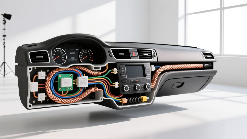
The Intersection of Luthier Standards and Automotive Electrical
When building custom hot rods, resto-mods, or high-fidelity automotive audio systems, fabricators and electrical engineers frequently encounter severe Electromagnetic Interference (EMI) and Radio Frequency Interference (RFI). Modern vehicles utilize Coil-on-Plug (COP) ignition systems, high-amperature smart alternators, and Pulse Width Modulation (PWM) fuel pumps. These components generate massive electrical noise that can easily infiltrate sensitive low-voltage circuits. To combat this, elite custom installers and OEM audio engineers borrow from the boutique audio and luthier world, specifically looking at the wire gauge for guitar and instrument amplifier applications to route sensitive signals without degradation.
While standard automotive primary wire is engineered for power delivery, signal transmission requires an entirely different approach. Understanding how to adapt instrument-grade wiring to the harsh, high-noise environment of a vehicle chassis is critical for custom builds integrating digital signal processors (DSPs), external instrument amplifiers, or highly sensitive ECU sensors like piezoelectric knock sensors.
Signal vs. Power: Why Guitar Wiring Specs Matter in Cars
When sourcing the correct wire gauge for guitar applications, builders and technicians typically look for 22 AWG to 24 AWG stranded, tinned copper wire with specific capacitance and shielding properties. In a vehicle, these exact specifications are critical for routing high-end RCA audio pre-outs, analog sensor extensions, and custom instrument amp bays.
Standard unshielded 18 AWG or 16 AWG primary wire (manufactured to SAE J1128 standards) is excellent for 12V power delivery to amplifiers and lighting. However, if used for low-voltage audio or sensor signals, it will act as an antenna, picking up 120Hz alternator ripple and high-frequency ignition arc noise. Conversely, the stranded construction and braided shielding found in premium instrument wire provide the flexibility needed to navigate tight automotive firewalls while maintaining a Faraday cage effect against RFI.
Capacitance and High-Frequency Roll-Off
One of the most critical, yet overlooked, specifications in both guitar wiring and automotive audio is cable capacitance, measured in picofarads per foot (pF/ft). High capacitance acts as a low-pass filter, rolling off high frequencies and resulting in a 'muddy' audio signal or a dampened sensor response. Premium instrument wire typically features a capacitance of around 20 to 30 pF/ft. When running 15-foot RCA extensions from a custom head unit to a trunk-mounted DSP like a Helix PRO or Mosconi, maintaining low capacitance is vital to preserve the transient response of the audio signal. For a deeper dive into how wire geometry affects audio frequencies, the Audioholics Wire Gauge Guide provides excellent foundational physics.
Technical Specification Chart: AWG and Application Matrix
The following matrix outlines the crossover between instrument-grade wire and specific automotive signal applications. This reference ensures you select the correct shielding and gauge for your specific build requirements.
| AWG Size | Stranding & Material | Shielding Type | Capacitance | Primary Automotive Application |
|---|---|---|---|---|
| 22 AWG | Stranded, Tinned Copper | Braided Copper (95%) | ~30 pF/ft | Custom RCA pre-outs, DSP analog inputs, auxiliary instrument amp bays. |
| 24 AWG | Stranded, Bare Copper | Foil + Braided Drain | ~22 pF/ft | O2 sensor extensions, wideband lambda routing, high-impedance pickups. |
| 20 AWG | Multi-Strand, Tinned | Concentric Spiral Shield | ~45 pF/ft | Low-frequency subwoofer line drivers, turntable grounding in custom audio. |
| 18 AWG | Coaxial, Silver-Plated | Dual-Braid (Foil/Braid) | ~15 pF/ft | Ultra-high-fidelity digital audio (S/PDIF), sensitive ECU knock sensor routing. |
Shielding Topologies: Braided vs. Foil in High-Noise Environments
The shield in instrument and automotive signal wire serves two purposes: it blocks external EMI from entering the signal path, and it provides a low-impedance return path for noise to ground. When adapting the wire gauge for guitar and instrument builds to automotive use, the choice of shield is paramount.
- Braided Copper Shield: Commonly found in vintage-style push-back cloth wire and premium instrument cables. It offers excellent flexibility and high tensile strength, making it ideal for automotive harnesses that experience chassis vibration and temperature cycling. The physical mass of the copper braid provides superior low-frequency noise rejection (e.g., alternator whine).
- Foil Shield with Drain Wire: Provides 100% coverage, making it highly effective against high-frequency RFI generated by COP ignition coils and spark plug arcs. However, foil is brittle and can crack if bent repeatedly. It is best used in static automotive harnesses, such as an engine bay sensor loom that is zip-tied and secured, rather than in a door jam where constant flexing occurs.
Adapting TS and TRS Connectors to Automotive Harnesses
In custom builds where a vehicle features an integrated instrument amplifier bay (e.g., a hot rod with a built-in Fender Twin Reverb or a boutique pedalboard), builders must interface standard 1/4-inch Tip-Sleeve (TS) or Tip-Ring-Sleeve (TRS) Switchcraft jacks with automotive-grade connectors like the Deutsch DT series to ensure water and vibration resistance.
Mapping a TRS Balanced Signal to a 3-Pin Deutsch DT Connector:
- Pin 1 (Tip / Signal+): Solder the 22 AWG inner signal core. Use Kester 44 rosin-core solder (60/40) for optimal wetting and electrical conductivity.
- Pin 2 (Ring / Signal-): Solder the secondary signal core (for balanced DSP outputs).
- Pin 3 (Sleeve / Shield): Solder the braided shield and bare drain wire. Critical Note: To prevent ground loops, the shield should typically be grounded at the receiver end (the amplifier or DSP) and left floating or wrapped in heat shrink at the source end.
Routing, Grounding, and Star Ground Topologies
Even the most expensive, meticulously shielded instrument wire will fail to reject noise if the vehicle's grounding topology is flawed. The most common cause of alternator whine in custom audio and sensor builds is the ground loop. This occurs when there are multiple paths to ground with varying electrical potentials, causing current to flow through the wire's shield.
To resolve this, elite installers utilize a Star Ground Topology. In this configuration, all audio component grounds (head unit, DSP, amplifiers) and sensitive sensor grounds are routed to a single, massive distribution block bolted directly to the vehicle chassis. The chassis connection point must be sanded down to bare, shiny metal, treated with an anti-oxidant compound (like Noalox), and torqued to the manufacturer's specification. By ensuring all components share the exact same ground potential, the voltage differential across the wire shields drops to zero, eliminating the loop.
Troubleshooting Decision Tree: Signal Degradation and Noise
When integrating instrument-grade wiring into a vehicle, use this diagnostic tree to isolate signal issues:
- Symptom: High-pitched whine that rises and falls with engine RPM.
- Cause: Shield grounded at both ends, creating a ground loop, or signal wire routed parallel to the alternator output cable.
- Fix: Lift the shield ground at the source end. Ensure signal wires cross power wires at a strict 90-degree angle, never running parallel.
- Symptom: Audio sounds 'muffled' or lacks high-end clarity; O2 sensor response feels sluggish.
- Cause: Excessive cable capacitance due to using cheap, high-pF/ft wire over a long distance (15+ feet).
- Fix: Replace with low-capacitance (under 25 pF/ft) 22 AWG or 24 AWG silver-plated stranded wire.
- Symptom: Intermittent signal dropouts over bumps.
- Cause: Solid-core wire used instead of stranded, leading to work-hardening and micro-fractures from chassis vibration.
- Fix: Never use solid-core wire in automotive applications. Replace with multi-strand tinned copper wire and use adhesive-lined marine heat shrink on all terminations.
Termination and Soldering Standards
The termination of the wire is just as critical as the wire itself. When working with the delicate stranding of 22 AWG or 24 AWG instrument wire, mechanical crimps alone are often insufficient due to the low surface area and the risk of strand shearing. Soldering is mandatory. Always use a temperature-controlled soldering station set between 350°C and 380°C. Avoid acid-core plumbing solders at all costs, as the corrosive flux will rapidly destroy the copper stranding and create high-resistance joints. For automotive environments, always seal the soldered joint with dual-wall, adhesive-lined heat shrink tubing. The inner thermoplastic adhesive melts and flows into the wire strands, creating a waterproof, vibration-proof seal that prevents galvanic corrosion from under-hood humidity and road salts.
Conclusion
By understanding the nuances of the wire gauge for guitar and instrument applications, automotive builders can drastically improve the fidelity of custom audio systems and the reliability of sensitive ECU sensors. The crossover of luthier standards—focusing on low capacitance, premium stranding, and high-coverage shielding—provides a robust defense against the harsh electrical noise inherent in modern vehicles. Whether you are wiring a boutique pedalboard into a custom center console or routing a wideband O2 sensor through a noisy engine bay, respecting these technical specifications ensures a clean, noise-free signal every time.