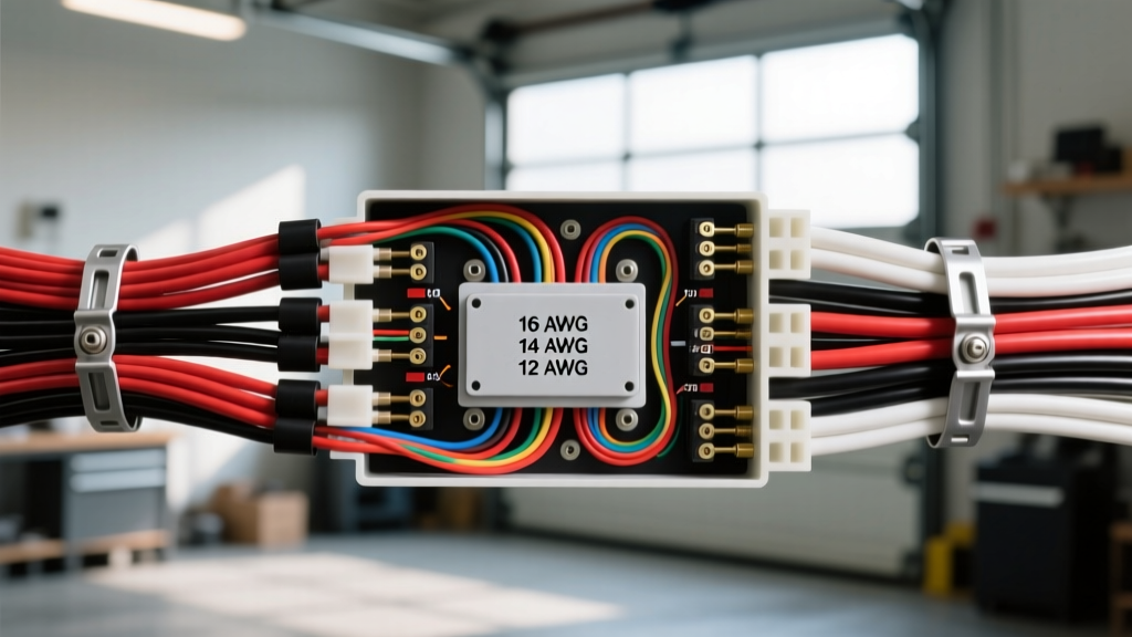
Why You Need a Speaker Wire Gauge Calculator for Car Audio
When upgrading your vehicle's audio system, selecting the correct wire size is just as critical as choosing the right amplifier or speakers. While a factory head unit pushing 15 to 22 watts RMS might function adequately with thin 18 AWG wire, aftermarket amplifiers delivering 75 to 150+ watts RMS per channel demand a precise approach. Using a dedicated speaker wire gauge calculator ensures you account for the specific electrical variables of your build, preventing power loss, thermal issues, and degradation of your system's damping factor.
The damping factor is the amplifier's ability to control the mechanical movement of the speaker cone, particularly at low frequencies. If your speaker wire is too thin, its electrical resistance increases. This added resistance acts as a buffer between the amplifier and the speaker voice coil, resulting in 'muddy' or 'boomy' bass response because the amplifier cannot properly brake the speaker's momentum. According to the engineering principles outlined by BCAE1, the total resistance of your speaker wire run should never exceed 5% of the speaker's nominal impedance. A proper calculation prevents this acoustic degradation.
The Core Variables: What the Calculator Needs
To accurately determine the required American Wire Gauge (AWG), a speaker wire gauge calculator requires four specific data points. Guessing these values often leads to overbuying heavy, difficult-to-route cable or underbuying wire that chokes your system's performance.
- Amplifier RMS Output: Always use the continuous RMS (Root Mean Square) wattage rating at the specific ohm load you are running, never the 'Peak' or 'Max' marketing numbers.
- Speaker Impedance (Ohms): Standard car speakers are typically 4 ohms, but subwoofers and component sets can be 2 ohms or even 1 ohm when wired in parallel. Lower impedance draws more current, requiring thicker wire.
- Total Wire Length: This is the one-way distance from the amplifier's output terminals to the speaker terminals, not the total round-trip length. You must account for hidden routing through A-pillars, under carpets, and through door hinges.
- Acceptable Voltage Drop: For high-fidelity car audio, a 5% loss is the standard threshold used in professional calculations.
Step 1: Determine Your Amplifier's True RMS Output
Check your amplifier's owner's manual for the RMS rating at the exact ohm load you are wiring. For example, a 4-channel amplifier might output 75 watts RMS per channel at 4 ohms, but 120 watts RMS per channel at 2 ohms. If you are wiring dual 4-ohm voice coil subwoofers in parallel to present a 1-ohm load to a monoblock amplifier, your current draw increases massively, drastically changing the output of your speaker wire gauge calculator.
Step 2: Measure the Exact Wire Run Length
Do not estimate the distance in a straight line. In a vehicle, wire must route around the transmission tunnel, under the center console, up the A-pillar, and through the door boot. Add at least 3 to 5 feet to your straight-line measurement to account for service loops, drip loops, and connections at the distribution block or crossover network.
Automotive Speaker Wire Gauge Chart (AWG Reference)
The following table provides a baseline reference based on standard calculations for Oxygen-Free Copper (OFC) wire. Note that if you are using Copper-Clad Aluminum (CCA) wire, you must increase the wire thickness by at least one full AWG size to compensate for CCA's 40% higher electrical resistance.
| Run Length (One-Way) | 4-Ohm Speaker (Up to 100W RMS) | 2-Ohm Speaker (Up to 200W RMS) | 1-Ohm Subwoofer (Up to 500W RMS) |
|---|---|---|---|
| 0 - 10 Feet | 16 AWG | 14 AWG | 10 AWG |
| 10 - 20 Feet | 14 AWG | 12 AWG | 8 AWG |
| 20 - 30 Feet | 12 AWG | 10 AWG | 6 AWG |
| 30+ Feet (Subwoofers in Trunk) | 10 AWG | 8 AWG | 4 AWG |
For comprehensive automotive cable insulation and temperature rating standards, installers should refer to the SAE J1128 specification, which dictates the thermal and chemical resistance required for wires routed through harsh engine bay and chassis environments.
Practical Installation and Routing Guide
Once your speaker wire gauge calculator has dictated the correct AWG, the physical installation presents its own set of challenges. Thicker wire (like 12 AWG or 10 AWG) is significantly harder to route through tight vehicle grommets.
Choosing the Right Wire Type and Jacket
Always select stranded Oxygen-Free Copper (OFC) wire with a flexible PVC or Teflon jacket. Avoid solid-core wire, as the constant vibrations of a vehicle chassis will cause solid copper to work-harden, snap, and create intermittent open circuits over time. For runs passing near exhaust components or through the firewall, use a high-temperature Teflon-jacketed wire or slide the wire inside a fiberglass fire sleeve.
Routing Through Door Hinges and Firewalls
The most difficult part of any car audio installation is passing wire from the cabin into the doors. Never simply pierce the factory rubber door boot with a screwdriver. Instead, remove the interior door panel and the lower kick panel. Locate the factory rubber accordion boot. Use a 1/4-inch flexible fiberglass fish tape, spray it with a silicone-based lubricant, and gently feed it through the existing factory grommet. Once the fish tape emerges in the door cavity, tape your speaker wire securely to the tape using electrical tape, creating a smooth, tapered bullet shape. Pull the wire through slowly, ensuring it does not catch on the window regulator tracks or the power lock actuator rods.
Termination and Connector Types
Never leave bare wire wrapped around speaker terminals. The constant humidity and temperature fluctuations inside a car door will cause bare copper to oxidize, creating a high-resistance diode effect that ruins audio quality. For 16 AWG and 14 AWG wire, use insulated female spade connectors. Strip exactly 3/8-inch of insulation, twist the strands tightly, and use a ratcheting crimping tool to secure the connector. For 12 AWG and larger wire terminating at a subwoofer, use ring terminals and secure them to the amplifier's set-screw terminals. For the ultimate connection, solder the wire directly to the speaker's crossover network using 60/40 rosin-core solder and seal the connection with adhesive-lined dual-wall heat shrink tubing.
Troubleshooting Common Gauge and Routing Errors
Even with the right calculations, physical installation errors can mimic the symptoms of incorrect wire sizing. Use this diagnostic tree to troubleshoot your system.
- Symptom: Bass sounds 'loose' or lacks punch at high volumes.
Cause: Wire gauge is too thin, or you are using CCA wire instead of OFC, resulting in a low damping factor.
Fix: Use a digital multimeter to measure the DC resistance of the wire run. If it exceeds 5% of the speaker's impedance, replace the wire with a thicker OFC gauge. - Symptom: Alternator whine or engine RPM noise in the speakers.
Cause: Speaker wires were routed parallel to the vehicle's alternator power wire or ignition harness.
Fix: Speaker wires carry high-voltage, high-current amplified signals and are generally immune to alternator whine (which typically plagues low-voltage RCA signal cables). However, if the speaker wire is damaged or poorly shielded, it can induce noise. Ensure speaker wires cross power wires at strict 90-degree angles. - Symptom: Amplifier goes into thermal protection mode during heavy bass transients.
Cause: The speaker wire gauge is too small for a low-impedance (1-ohm or 2-ohm) load, causing the wire to heat up and reflect resistance back to the amplifier's output stage.
Fix: Recalculate using the speaker wire gauge calculator for your specific ohm load and upgrade to a heavier gauge, ensuring all terminal set-screws are torqued to the manufacturer's specification to prevent arcing.
For further reading on vehicle-specific wiring integration and factory harness pinouts, consult the vehicle-specific guides available through Crutchfield's Learning Center, which provides excellent baseline data for matching aftermarket wire to factory color codes.