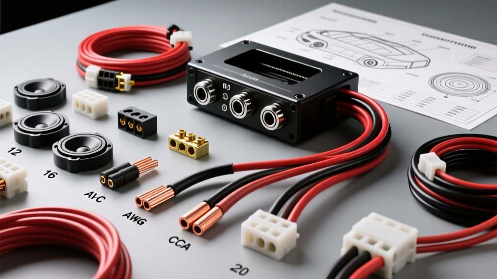
The Physics of Mobile Audio: Why Gauge Calculation Matters
Upgrading a vehicle's sound system requires more than just swapping out factory paper cones for premium poly-injection drivers. The conduit delivering the audio signal—the speaker wire—is the most overlooked component in mobile audio. To properly calculate speaker wire gauge, you must understand the relationship between electrical resistance, impedance, and the amplifier's damping factor. In a 12-volt automotive environment, voltage drop and thermal compression can severely limit the dynamic range of your system if the wire is undersized.
Unlike household audio, car audio systems operate in high-vibration, high-temperature environments. Routing wires through door jambs, under carpeting, and near exhaust tunnels adds physical stress and thermal variables. According to SAE International Standard J1128, automotive wiring must withstand specific thermal and abrasion thresholds. While speaker wire does not carry the same high amperage as a starter cable, undersizing it increases the resistance in series with the speaker. This artificially raises the total impedance, robbing your amplifier of power and destroying the damping factor—the amplifier's ability to control the speaker cone's movement, which is critical for tight, accurate bass response.
How to Calculate Speaker Wire Gauge for Your Build
The industry standard rule of thumb is that the total resistance of your speaker wire should not exceed 5% of the speaker's nominal impedance. If you are driving a standard 4-ohm car audio component set, the wire resistance should remain below 0.2 ohms. To calculate speaker wire gauge accurately, you need three variables: the maximum RMS wattage, the speaker's impedance (in ohms), and the total length of the wire run in feet.
The Calculation Formula
Resistance per foot varies by American Wire Gauge (AWG). Copper has a specific resistance of approximately 10.37 ohms per circular mil-foot. Using Ohm's Law and the resistivity of copper, we can determine the voltage drop across the wire run. For example, 16 AWG Oxygen-Free Copper (OFC) wire has a resistance of roughly 0.004 ohms per foot. If you run 15 feet of 16 AWG wire from your trunk-mounted amplifier to the front left door speaker (including the ground return path, making the total circuit 30 feet), the total resistance is 0.12 ohms. This is well within the 5% threshold for a 4-ohm load, making 16 AWG perfectly adequate for a 75-watt RMS channel.
However, if you are wiring a high-excursion 10-inch subwoofer rated at 500 watts RMS at 2 ohms, that same 0.12 ohms of wire resistance represents 6% of the load. This will result in a noticeable loss of electrical damping, causing the bass to sound 'muddy' or 'boomy' during rapid transients. For subwoofer applications, you must calculate speaker wire gauge with a stricter 2% resistance threshold, often necessitating 12 AWG or even 10 AWG wire for runs exceeding 10 feet.
Product Comparison: OFC vs. CCA Speaker Wire
When shopping for car audio wire, you will encounter two primary materials: Oxygen-Free Copper (OFC) and Copper-Clad Aluminum (CCA). Understanding the difference is critical when you calculate speaker wire gauge, as their conductivity profiles dictate which size you must purchase.
| Material | Conductivity | Weight | Corrosion Resistance | Sizing Adjustment |
|---|---|---|---|---|
| OFC (Oxygen-Free Copper) | 100% (Baseline) | Heavy | Excellent | Use standard AWG charts |
| CCA (Copper-Clad Aluminum) | ~60% of Copper | Light | Poor (Internal oxidation) | Upsize by 1 to 2 AWG |
OFC Wire: This is the premium standard for mobile audio. OFC is refined to remove oxygen inclusions, resulting in a purer copper strand that conducts electricity efficiently and resists internal corrosion. When you calculate speaker wire gauge using standard charts, they assume OFC. It is highly flexible, surviving the repeated bending required when routing through factory door hinge boots.
CCA Wire: CCA features an aluminum core with a thin copper electroplated outer layer. While it looks like copper on the outside, aluminum has roughly 60% of the conductivity of copper. This means a 16 AWG CCA wire has the same resistance as an 18 AWG or even 20 AWG OFC wire. Furthermore, if the outer copper layer is nicked during installation, moisture can penetrate and cause galvanic corrosion inside the wire, eventually leading to an open circuit. If budget constraints force you to use CCA, you must upsize your gauge by at least one step (e.g., buy 14 AWG CCA to achieve the performance of 16 AWG OFC).
Automotive Speaker Wire Gauge Selection Chart
The following chart assumes the use of high-strand-count OFC wire. Distances represent the one-way run from the amplifier or head unit to the speaker location. Remember that the electrical circuit includes both the positive and negative legs, so a 10-foot physical run equals 20 feet of total wire in your resistance calculations.
| AWG Size | Max Wattage (4-Ohm Load, 15ft Run) | Max Wattage (2-Ohm Load, 15ft Run) | Recommended Automotive Application |
|---|---|---|---|
| 18 AWG | 50W RMS | 25W RMS | Factory head unit replacements, rear deck 6x9s |
| 16 AWG | 100W RMS | 50W RMS | 4-channel amp to door component sets, coaxials |
| 14 AWG | 200W RMS | 100W RMS | High-power 6.5" mid-bass drivers, long runs to dash |
| 12 AWG | 400W RMS | 200W RMS | Subwoofer enclosures, 8" midrange drivers |
| 10 AWG | 800W RMS | 400W RMS | High-SPL 12"/15" subwoofers, competition builds |
Standard EIA Color Codes & Automotive Routing
Proper identification is essential for troubleshooting and maintaining phase coherence. The Consumer Technology Association (CTA), formerly the EIA, established standard color codes for automotive speaker wiring to ensure left/right and positive/negative consistency across aftermarket head units and harness adapters like those from Metra and Axxess.
- Left Front: White (Positive) / White with Black Stripe (Negative)
- Right Front: Gray (Positive) / Gray with Black Stripe (Negative)
- Left Rear: Green (Positive) / Green with Black Stripe (Negative)
- Right Rear: Purple (Positive) / Purple with Black Stripe (Negative)
Routing Warning: When running 16 AWG or 14 AWG wire from the cabin into the doors, you must pass through the factory rubber door jamb boot. Never use T-taps or scotch locks to splice into factory wiring; these connectors pierce the insulation, exposing bare copper to humidity and causing rapid green corrosion. Always cut the factory plug, solder your CTA-colored OFC wire using rosin-core solder, and seal the joint with dual-wall adhesive-lined heat shrink. This prevents moisture wicking and maintains the structural integrity of the harness.
Connector Selection and Termination Methods
How you terminate the wire at the speaker basket is just as critical as the gauge itself. High-strand OFC wire can fray easily. For door speakers, use female quick-disconnect spade terminals (typically 0.187-inch or 0.205-inch widths) crimped with a ratcheting crimp tool. Soldering directly to the speaker terminal is discouraged in mobile environments because the constant vibration and thermal expansion/contraction of the door panel can cause rigid solder joints to crack and snap the speaker's copper tinsel lead.
For subwoofer terminals, which often feature heavy-duty spring posts or binding posts, use large ring terminals or spade lugs. Ensure the crimp is mechanically sound; a poorly crimped 10 AWG terminal will create a high-resistance bottleneck, entirely defeating the purpose of using heavy-gauge wire.
Real-World Failure Modes and Troubleshooting
Even when you calculate speaker wire gauge correctly, installation errors can mimic the symptoms of undersized wire. Use this decision tree to diagnose common mobile audio issues:
Symptom: Bass lacks punch and sounds 'one-note'
- Cause A: Wire gauge is too thin (exceeding 5% resistance threshold), destroying the amplifier's damping factor.
- Cause B: Out-of-phase wiring. If the left and right subwoofers are wired with reversed polarity (positive to negative), they will suffer from acoustic cancellation in the low frequencies. Verify your CTA color codes and use a 9V battery pop test to confirm cone excursion direction.
Symptom: High frequencies sound harsh or distorted at high volumes
- Cause A: Thermal compression in the crossover network. If the passive crossover is mounted in a door panel exposed to direct sunlight, the inductors can overheat. Ensure your wire gauge is sufficient so that excess heat isn't being generated by the wire itself before reaching the crossover.
- Cause B: Stray magnetic interference. If speaker wires are routed parallel to high-current power cables or RCA interconnects, they can pick up alternator whine. Always cross power and speaker wires at 90-degree angles.
For further technical specifications on mobile audio wiring and installation best practices, refer to the Crutchfield Car Speaker Wire Guide and always consult your vehicle's factory service manual before drilling or routing wires near SRS side-impact airbag modules, which are universally identified by yellow wiring looms.