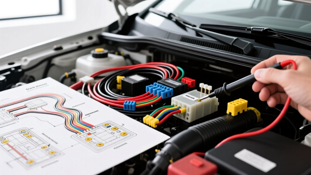
Understanding the Subaru Outback Electrical Architecture
Diagnosing Subaru Outback electrical problems requires a basic understanding of how the vehicle's wiring harness is routed and managed. Unlike many transverse-engine vehicles, the Subaru Outback utilizes a longitudinally mounted Boxer engine and Symmetrical All-Wheel Drive. This unique layout dictates a split-wiring architecture, where the engine harness and dash harness mate at specific bulkhead connectors (like the B11 and F49 connectors) near the firewall. Furthermore, modern Outbacks rely heavily on the Body Integration Unit (BIU) and CAN bus networks to manage everything from door locks to engine immobilizers. For beginners, this complexity can seem daunting, but by applying systematic electrical troubleshooting fundamentals, you can isolate and repair most faults without dealership-level scan tools.
Essential Diagnostic Tools for Beginners
Before diving into specific Subaru Outback electrical problems, you must equip yourself with the right tools. Using the wrong tool can lead to misdiagnosis or, worse, damage to sensitive modules like the BIU or Transmission Control Module (TCM).
- Digital Multimeter (DMM): You need a DMM with a high-impedance input (minimum 10 Megohms). Low-impedance meters can draw enough current to trigger false readings or damage solid-state Subaru circuits.
- Logic Probe or LED Test Light: Never use a traditional incandescent test light on Outback CAN bus wiring, airbag (SRS) circuits, or ECU sensor wires. The filament draws too much amperage and can fry the driver circuit. Always use an LED logic probe or your DMM.
- Wire Piercing Probes: Avoid back-probing Subaru weather-pack connectors with paperclips or standard pins, as this spreads the terminals and causes future intermittent faults. Use dedicated, thin back-probe pins or insulation-piercing probes for temporary testing.
Symptom-Cause-Fix Decision Tree: Common Outback Issues
Below is a beginner-friendly decision tree designed to help you systematically isolate the most frequently reported Subaru Outback electrical problems.
Symptom 1: Parasitic Draw (Battery Dead Every Morning)
Probable Cause: A faulty aftermarket radio harness, a sticking EFI Main Relay, or corrosion in the B11 BIU connector preventing the CAN bus from going to 'sleep'.
Diagnostic Step: Perform a fuse voltage drop test. Instead of breaking the circuit to insert your ammeter (which can wake up the BIU and reset the sleep timer), set your DMM to DC millivolts (mV). Measure across the two exposed test points on top of each Mini/ATO fuse in the interior and engine bay fuse boxes.
The Fix: Identify the fuse with the highest mV reading. Consult the fuse voltage drop chart below to calculate the exact amperage draw. If the draw is on the ACC circuit, check the radio's constant vs. switched power wiring. If it is on the BIU circuit, inspect the B11 connector for green crusty corrosion (copper oxide) and clean it with electrical contact cleaner.
Symptom 2: Intermittent Crank, No-Start (Fuel Pump Silent)
Probable Cause: Poor ground connection at G10 (left strut tower) or a failing EFI Main Relay.
Diagnostic Step: Turn the key to the ON position. Listen for the fuel pump prime. If silent, locate the EFI relay in the engine bay fuse box. Using your DMM, check for 12V at the relay coil power pin (typically a Red/Blue wire). Next, check the coil ground circuit (typically a Black/White wire) for continuity to the chassis.
The Fix: If power and ground are present at the relay coil but the switch contacts do not pass 12V to the fuel pump (Black/White wire, 18 AWG), replace the relay. If the ground circuit shows high resistance, unbolt the G10 ground point on the strut tower, sand away oxidation, and reinstall with dielectric grease.
Symptom 3: Dash Lights Flickering and CAN Bus Codes (U0073)
Probable Cause: CAN bus termination resistor failure, chafed twisted-pair wiring near the steering column, or low system voltage from a failing alternator diode trio.
Diagnostic Step: Access the OBD2 Data Link Connector (DLC) under the dash. Set your DMM to Ohms (ensure the vehicle battery is disconnected to prevent back-feeding). Measure resistance between Pin 6 (CAN High) and Pin 14 (CAN Low).
The Fix: A healthy Subaru CAN bus will read exactly 60 ohms (two 120-ohm terminating resistors in parallel). If you read 120 ohms, one of the terminating modules (usually the ECU or the BIU) has lost power or ground. If you read infinite resistance (OL), the CAN wiring is broken or a resistor has failed. Trace the White (CAN-H) and Red (CAN-L) wires from the DLC back to the first splice point.
Mastering the Voltage Drop Test on Subaru Grounds
Many beginners attempt to test grounds by checking for continuity (Ohms) with the battery disconnected. However, a single strand of 20 AWG wire can show 0.1 ohms of continuity but will completely fail to carry the 15 amps required by an oxygen sensor heater circuit. The only accurate way to diagnose Subaru Outback ground problems is a live voltage drop test.
- Leave the circuit powered and under load (e.g., turn on the headlights or command the cooling fan).
- Set your DMM to DC Volts.
- Place the Red probe on the negative terminal of the battery.
- Place the Black probe on the metal component you are trying to ground (e.g., the engine block or the metal casing of the BIU).
- Read the voltage. A healthy Subaru ground circuit should show a voltage drop of less than 0.10V (100mV). Any reading above 0.20V indicates unacceptable resistance in the ground path.
For deeper technical methodologies on this procedure, refer to the Fluke Automotive Voltage Drop Testing Guide, which outlines industry-standard practices for high-current and low-current circuits.
CAN Bus and OBD2 Port Diagnostics
Subaru transitioned heavily into CAN bus (Controller Area Network) architecture in the mid-2000s. The CAN bus is a twisted-pair network that allows modules to share data without running hundreds of individual wires. When diagnosing communication-based Subaru Outback electrical problems, you must respect the physical layer of this network.
The OBD2 port (DLC) is your gateway to the CAN bus. According to the SAE J1962 Standard, the pinout for CAN communication is standardized, but Subaru utilizes specific wire colors in the harness leading up to the connector. Pin 6 is CAN High (typically White wire), and Pin 14 is CAN Low (typically Red wire). If you back-probe these pins with the ignition ON and the network active, you should see CAN-H hovering around 2.6V and CAN-L hovering around 2.4V. If both read 12V, the transceiver inside the BIU or ECU has shorted to power.
Subaru Outback Wiring & Connector Reference Table
Use the following reference table when tracing circuits and verifying pinouts during your diagnostic process. Always cross-reference with the specific year's wiring diagram available via the Subaru Technical Information System (STIS), as minor color variations occur between generations.
| Component / Connector | Pin / Location | Wire Color | AWG | Function / Specification |
|---|---|---|---|---|
| B11 Connector (BIU Main) | Pin 1 | Red/White | 14 AWG | Constant +12V Battery Feed |
| B11 Connector (BIU Main) | Pin 14 | Black/White | 14 AWG | Main Chassis Ground (Verify at G40) |
| OBD2 DLC | Pin 6 | White | 20 AWG | CAN High (Target: 2.6V active) |
| OBD2 DLC | Pin 14 | Red | 20 AWG | CAN Low (Target: 2.4V active) |
| EFI Main Relay | Pin 1 (Coil) | Red/Blue | 18 AWG | Switched Ignition +12V |
| EFI Main Relay | Pin 2 (Coil) | Black/White | 18 AWG | ECU Controlled Ground |
| Fuel Pump Assembly | Power Pin | Black/White | 12 AWG | High Current Pump Feed (Fused at 15A) |
| Engine Ground G10 | Left Strut Tower | Black (No Trace) | 8 AWG | Engine Block to Chassis Main Ground |
Fuse Voltage Drop Conversion (Parasitic Draw)
When performing the mV drop test across fuses to find a parasitic draw, use this baseline conversion chart for standard Subaru Mini fuses:
- 10 mV drop on a 10A Mini Fuse = Approx. 0.65 Amps (650mA) draw.
- 5 mV drop on a 15A Mini Fuse = Approx. 0.70 Amps (700mA) draw.
- 2 mV drop on a 20A Mini Fuse = Approx. 0.40 Amps (400mA) draw.
Note: A normal, sleeping Subaru Outback should have a total parasitic draw of less than 50mA (0.05A) after 20 minutes with the doors locked and the BIU asleep.
Final Thoughts for Beginners
Tackling Subaru Outback electrical problems does not require a degree in electrical engineering. By relying on systematic voltage drop testing, respecting the sensitivity of the CAN bus network, and utilizing accurate wiring diagrams, you can confidently diagnose everything from a simple dead battery to complex BIU communication faults. Always start with the power and ground sources before condemning expensive control modules.