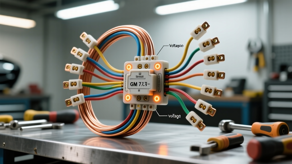
The Master Gateway: Why the Ignition Switch Dictates Electrical Health
When drivers ask, "can a bad ignition switch cause electrical problems?" the short answer is an absolute yes. The ignition switch is not merely a mechanical lock; it is the primary high-current power distribution gateway for the entire vehicle. Every time you turn the key, a complex series of internal copper and silver-cadmium oxide contacts slide against one another to route battery voltage to the Powertrain Control Module (PCM), fuel pump relays, HVAC blower motors, and body control modules (BCM).
Because the ignition switch handles massive electrical loads—often exceeding 40 amps collectively across its circuits—it is highly susceptible to thermal degradation, carbon tracking, and terminal fretting. When these internal contacts degrade, they don't just fail to start the engine; they introduce severe voltage drops that can mimic failing alternators, dead batteries, or fried computers. To understand how a bad ignition switch causes cascading electrical problems, we must perform a complete wiring diagram walkthrough of one of the most common automotive switches on the road: the GM 7-Pin Delphi Packard column-mounted ignition switch, widely used in GMT800 trucks (Silverado/Sierra) and W-body sedans.
Complete Wiring Diagram Walkthrough: GM 7-Pin Metri-Pack Connector
The GM 7-pin ignition switch utilizes a Delphi (now Aptiv) Metri-Pack 280 series connector for high-current feeds and a Metri-Pack 150 series cavity for low-current security signals. The switch itself is typically located on the steering column, actuated by a rack and pinion gear connected to the lock cylinder.
| Pin | Circuit Name | Wire Color | AWG | Function & Load Profile |
|---|---|---|---|---|
| A | Battery Feed (B+) | Red | 10 AWG | Constant 12V+ from the main fusible link. Feeds the switch internally. |
| B | Accessory (ACC) | Brown | 12 AWG | Hot in ACC and RUN. Powers radio, wipers, and power windows. |
| C | Ignition 1 (IGN1) | Pink | 12 AWG | Hot in RUN and BULB TEST. Powers PCM, fuel injectors, and dash cluster. |
| D | Ignition 3 (IGN3) | Pink | 12 AWG | Hot in RUN only. Powers HVAC blower, ABS module, and airbags. |
| E | Crank (START) | Yellow | 12 AWG | Hot only in START. Triggers the starter solenoid relay. |
| F | Passlock Data | White | 18 AWG | Security sensor signal to the BCM. Varies between 2.5V and 5.0V. |
| G | Ground / Shield | Black | 18 AWG | Reference ground for the Passlock Hall-effect sensor. |
How Internal Switch Failures Cascade Through the Harness
Understanding the pinout reveals exactly how specific failure modes create bizarre, seemingly unrelated electrical problems across the vehicle.
1. Carbon Tracking and PCM Starvation (The Pink Wire Issue)
Pin C (Pink, 12 AWG) supplies the IGN1 circuit, which wakes up the PCM and powers the fuel pump relay. Over time, the internal contact pad for Pin C develops carbon tracking from micro-arcing when the key is turned. This carbon buildup acts as a resistor. Instead of delivering 12.6V to the PCM, the switch may deliver 10.8V under load. The PCM's internal voltage regulator struggles to step this down to a clean 5V reference for sensors, resulting in erratic TPS readings, random misfire codes (P0300), and stalling. The electrical problem isn't the PCM; it is a voltage drop originating inside the ignition switch.
2. Thermal Melt on the Main Battery Feed (Pin A)
Pin A (Red, 10 AWG) carries the total combined amperage of the ACC, IGN, and START circuits. If the female Metri-Pack 280 terminal in the harness connector loses its spring tension (terminal spread), the connection resistance increases. According to Joule's Law (P = I²R), even a minor increase in resistance under a 30-amp load generates massive heat. This melts the Delphi plastic housing around Pin A, causing the red wire to pull back. This results in an intermittent total loss of electrical power to the dash, often misdiagnosed as a bad battery cable or failing alternator.
3. The Crank Circuit Voltage Drop (No-Start Condition)
Pin E (Yellow, 12 AWG) sends the crank signal to the starter relay. The starter solenoid requires a minimum of 9.5V to engage the Bendix gear and close the main starter contacts. If the internal switch contacts for the START position are pitted, a 3-volt drop can occur. The relay receives only 9.0V, resulting in a rapid clicking noise or a complete no-crank condition. Mechanics often replace the starter or battery, only to find the root cause was the ignition switch failing to pass adequate cranking voltage.
Diagnostic Decision Tree: Isolating the Switch vs. Downstream Faults
Before tearing into the steering column, use this logical decision tree to confirm the ignition switch is the root cause of the electrical anomaly.
- Symptom: Dash lights flicker, radio resets while driving, or PCM throws low-voltage codes.
- Test: Monitor Pin C (Pink) and Pin D (Pink) with a digital multimeter (DMM) while wiggling the key.
- Result: If voltage fluctuates by more than 0.5V, the internal switch contacts are worn. Fix: Replace ignition switch.
- Symptom: Vehicle cranks but will not start; Security light flashes.
- Test: Back-probe Pin F (White) and Pin G (Black) during the crank sequence.
- Result: If the Passlock voltage does not match the BCM's expected learned resistance value (usually around 2.8V - 3.2V), the switch's internal Hall-effect sensor is faulty. Fix: Replace switch and perform Passlock relearn.
Advanced Voltage Drop Testing Procedure
To definitively prove a bad ignition switch is causing electrical problems, you must perform a dynamic voltage drop test. Never pierce wires with a test light; use a high-impedance DMM like a Fluke 87V and back-probe the connector.
- Prepare the Circuit: Set your DMM to the DC Millivolt (mV) scale. Ensure the battery is fully charged (12.6V resting).
- Test the Main Feed (Pin A): Place the red probe on the battery positive post and the black probe on the back of the ignition switch connector at Pin A (Red wire). Turn the key to RUN and turn on the HVAC blower to max (loading the circuit). A healthy feed should show less than 50 mV (0.050V) drop.
- Test the Internal Contacts (Pin C & D): Place the red probe on the back of Pin A (Red wire) and the black probe on the back of Pin C (Pink wire). Turn the key to RUN. The voltage drop across the internal switch contact must be less than 150 mV (0.150V). If you read 300 mV or higher, the internal silver-cadmium contacts are degraded and causing downstream module starvation.
- Test the Crank Circuit (Pin E): Place the red probe on Pin A and the black probe on Pin E (Yellow). Have an assistant crank the engine. A drop exceeding 200 mV (0.200V) confirms the START contacts are pitted and restricting solenoid amperage.
Connector and Terminal Repair Specifications
Replacing the switch is only half the battle. Because ignition switches operate in high-vibration, high-heat environments, the female terminals in the harness connector often suffer from fretting corrosion. When servicing a GM 7-pin ignition switch, always inspect the Metri-Pack 280 terminals. If the brass plating is worn or the retention tangs are flattened, you must splice in a new pigtail (such as the ACDelco PT2255 or equivalent). Solder all splices using rosin-core solder and seal with dual-wall heat shrink tubing containing an adhesive lining to prevent moisture ingress and subsequent copper oxidation.
Authoritative References
- SAE J1113: Electromagnetic Compatibility Measurement Procedures and Limits - Society of Automotive Engineers (Guidelines on voltage drop tolerances for automotive PCM wake-up circuits).
- Delphi (Aptiv) Automotive Connection Systems Catalog - Metri-Pack 280 and 150 series terminal retention and current-carrying capacity specifications.
- Haynes Automotive Electrical Manual - Standard procedures for dynamic voltage drop testing and steering column switch diagnostics.