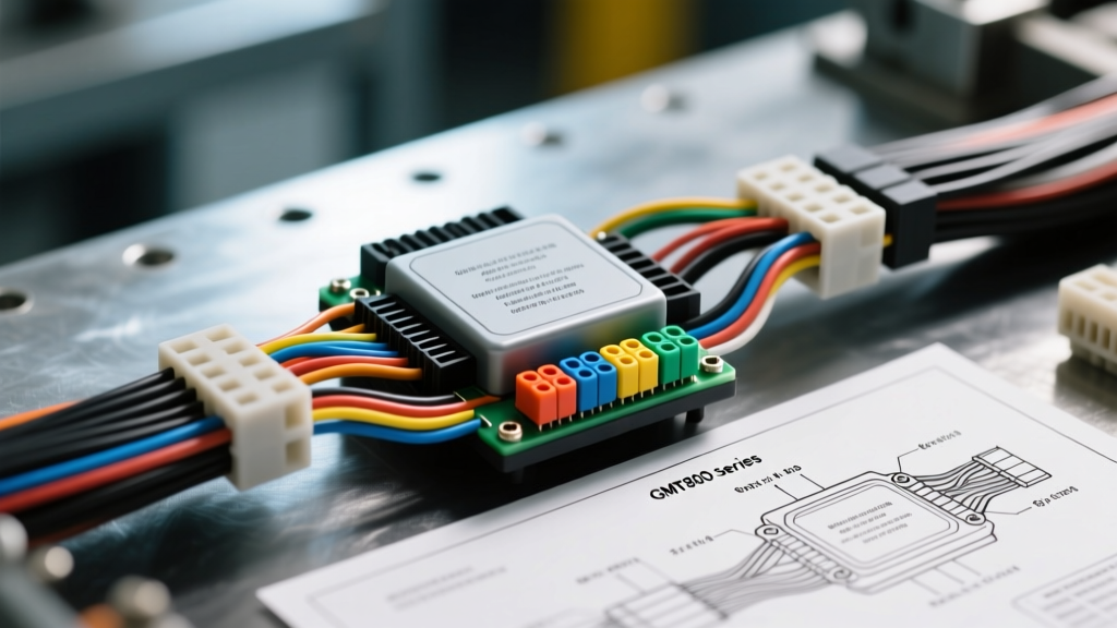
The Schematic-First Approach to Automotive Diagnostics
When diagnosing electrical problems in cars, the most critical mistake a technician can make is bypassing the wiring diagram in favor of guesswork or blind parts swapping. Modern vehicle networks are highly integrated, and a symptom in one circuit often originates in a completely different module. A wiring schematic is not just a map of wires; it is a logical flowchart of power distribution, module logic, and ground architecture. To effectively trace a fault, you must dissect the schematic into four distinct zones: Power Source and Protection, Control and Logic, Load, and Ground Return.
In this comprehensive walkthrough, we will trace a classic and frequently problematic circuit: the Body Control Module (BCM) commanded headlight and Daytime Running Lamp (DRL) system on the GM GMT800 platform (Silverado/Sierra 1999-2006). By following this exact methodology, you can apply the same systematic breakdown to any CAN-bus or multiplexed lighting circuit on modern vehicles.
Zone 1: Power Source and Protection
Every diagnostic walkthrough begins at the battery. According to the power distribution schematic, the headlight circuit originates at the positive battery post, traveling through a 10 AWG Red (RED) cable to the Underhood Electrical Center (UEC). Here, it passes through a 40A Mega Fuse before splitting into the lighting sub-circuits.
For the low beam headlamps, the power feeds into the HDLP 15A mini-fuse. Diagnostic Checkpoint: Before touching a single wire downstream, verify battery voltage at both sides of the HDLP fuse with a digital multimeter (DMM) referencing a known good engine block ground. If you read 12.4V on the feed side but 0V on the load side, the fault is isolated to the UEC internal bussing or a corroded fuse blade, saving you hours of chasing wires under the dash.
Zone 2: Control and Logic (Switch to BCM)
Unlike older vehicles where the headlight switch directly carried the 15A load to the lamps, the GMT800 uses the headlight switch as a low-current logic input. The switch sends a discrete voltage signal to the BCM via an 18 AWG Gray (GRY) wire.
This wire terminates at the BCM Connector C3 (a 24-pin black connector), specifically at Pin C3-15. When the driver rotates the switch to the 'Headlamp' position, the switch completes an internal resistor ladder, dropping the voltage on the GRY wire to a specific threshold (typically around 2.5V to 3.0V) that the BCM's analog-to-digital converter recognizes as a headlamp request.
Once the BCM validates the request and checks for conflicting inputs (like the park brake switch being engaged, which would inhibit DRLs), it commands the DRL relay. The BCM does this by providing a switched ground path on an 18 AWG Yellow (YEL) wire connected to Pin C3-16. This YEL wire travels to the DRL Relay coil terminal (Pin 85).
Zone 3: The Load and Ground Return
With the relay coil grounded by the BCM, the internal electromagnetic coil energizes, pulling the relay contacts closed. This bridges the high-current path from Relay Pin 30 (fed by the 15A HDLP fuse) to Relay Pin 87.
The load current now exits the relay on a 14 AWG Dark Green (DK GRN) wire, traveling through the engine harness bulkhead connector (C100) and into the forward lamp harness, ultimately reaching the left and right low beam headlamp connectors. Finally, the circuit completes through a 14 AWG Black (BLK) wire that grounds at G101, located on the left front fender inner panel behind the battery.
Technical Reference: GMT800 BCM Connector C3 Pinout
When back-probing the BCM, it is vital to use the correct T-pins to avoid spreading the female terminals inside the Molex connector. Below is the critical pinout for the lighting logic circuit on Connector C3.
| Pin | Wire Color | AWG | Function / Signal Description |
|---|---|---|---|
| C3-04 | BRN | 18 | Park Lamp Switch Signal Input |
| C3-15 | GRY | 18 | Headlamp Switch Signal Input (Resistor Ladder) |
| C3-16 | YEL | 18 | DRL Relay Coil Ground Control Output |
| C3-18 | DK BLU | 18 | Flash-to-Pass Relay Control Output |
| C3-24 | BLK | 14 | BCM Module Ground (Spliced to G200) |
Advanced Diagnostic Decision Tree
When diagnosing electrical problems in cars, use this symptom-to-action matrix to isolate the fault zone rapidly.
- Symptom: Headlamps inoperative, DRLs inoperative, but parking lamps work.
- Schematic Check: HDLP Fuse and DRL Relay.
- Action: Swap DRL relay with a known good horn relay. If headlamps work, replace relay. If not, check voltage at Relay Pin 30.
- Symptom: Headlamps work, but DRLs do not activate during the day.
- Schematic Check: Park brake switch and BCM inhibit logic.
- Action: Connect scan tool to BCM data list. Monitor 'Park Brake Switch' PID. If it reads 'Engaged' while the pedal is released, the fault is a misadjusted park brake switch or short to ground on the park brake signal wire, not the headlamp circuit.
- Symptom: Left headlamp dim, right headlamp normal brightness.
- Schematic Check: Load side wiring and Ground G101.
- Action: Perform a voltage drop test on the ground side of the left headlamp circuit.
The Fallacy of Continuity Testing
A pervasive error in automotive diagnostics is relying on the 'beep' or continuity function of a multimeter to verify a wire's integrity. According to the principles outlined in SAE J1128 standards for low-voltage primary cable, a single copper strand of 18 AWG wire will register less than 1 ohm of resistance and trigger a continuity beep. However, that single strand will instantly vaporize or cause severe voltage drop if asked to carry the 15 amps required by a headlamp circuit.
Instead, you must perform Voltage Drop Testing under load. To test the 14 AWG DK GRN load wire, leave the headlamps turned on. Place your DMM's red lead on the output side of the DRL relay (Pin 87) and the black lead directly on the headlamp connector's power terminal. A healthy 14 AWG wire carrying 5 amps should exhibit a voltage drop of no more than 0.2V (200mV). If your meter reads 1.5V, you have located a high-resistance fault—likely corrosion inside the C100 bulkhead connector or a crimp failure at a splice pack.
Navigating Splice Packs and Ground Distribution Charts
Wiring diagrams often hide the physical reality of the vehicle's harness. A schematic will show a simple dot indicating a splice, but in reality, this is often a physical Splice Pack (e.g., SP102) wrapped in friction tape deep inside the engine harness. The GMT800 service manuals provide a 'Splice Pack and Ground Location' chart. For instance, Ground G101 is not just a conceptual symbol; the chart specifies it is located on the left front fender, secured by an M6 bolt torqued to 9 Nm.
Corrosion at G101 is a notorious failure mode on these trucks, often caused by battery acid off-gassing or water intrusion past the fender liner. When diagnosing a dim headlamp or a bizarre 'back-feeding' issue where turning on the left turn signal causes the headlamp to flicker, always unbolt, wire-brush, and apply dielectric grease to the ground ring terminal before condemning the headlamp switch or BCM. For further diagnostic case studies and community-verified wiring anomalies, professional networks like iATN (International Automotive Technicians Network) remain an invaluable resource for cross-referencing schematic errors and harness chafing points that OEM manuals occasionally overlook.
Final Verification
Once the fault is repaired—whether it is a repinned BCM C3 connector, a cleaned G101 ground, or a replaced DRL relay—clear any historical BCM Diagnostic Trouble Codes (DTCs) such as U1000 (Class 2 Data Link Malfunction) or B2480 (Headlamp Control Circuit). Re-run the voltage drop tests to ensure the repair falls within the ASE standard repair thresholds of <0.1V for grounds and <0.2V for power feeds. Mastering the wiring diagram transforms electrical diagnostics from a frustrating guessing game into a precise, repeatable science.