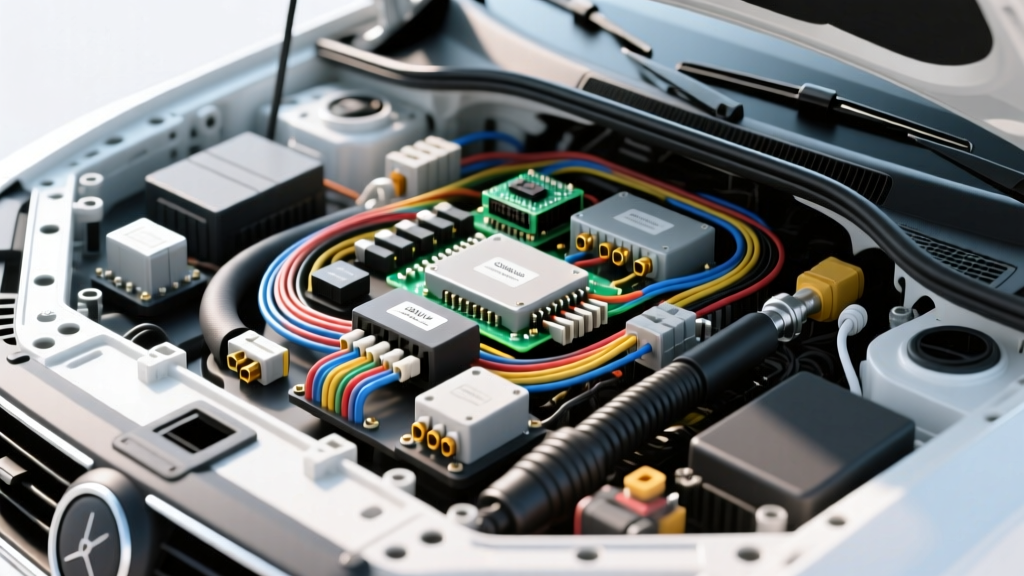
Automotive Electrical Triage: Matching the Fault to the Specialist
When a vehicle exhibits parasitic battery drain, intermittent module communication loss, or total electrical failure, the immediate question for fleet managers and DIYers is who to call for electrical problems. The modern automobile is not a single electrical system; it is a rolling network of multiplexed data buses, high-current discrete circuits, and proprietary fiber optics. Handing a Controller Area Network (CAN) bus topology fault to a general lube-and-tune mechanic will result in unnecessary parts swapping, while taking a simple 12-volt ground fault to a dealership will incur exorbitant diagnostic fees. This technical specification reference provides a definitive triage matrix to match your specific electrical fault signature to the correct level of automotive electrical specialist.
Technical Fault-to-Specialist Triage Matrix
Before making a service appointment, measure the circuit parameters to categorize the fault. Use this matrix to determine the required expertise level based on SAE network classifications.
| Fault Category | Technical Signature | Required Tooling | Who to Call |
|---|---|---|---|
| Discrete 12V/24V Power | Voltage drop > 0.1V per connection; blown fuses; high resistance | Digital Multimeter (DMM), Load Tester | General Auto Mechanic / DIY |
| CAN/LIN Network Faults | U-codes (e.g., U0100); 60-ohm termination failure; waveform distortion | DSO (Oscilloscope), Breakout Box | Certified Auto Electrician / L1 Tech |
| Proprietary / HV Systems | FlexRay sync loss; MOST optical attenuation; HV interlock trips | OEM Scan Tool, Fiber Optic Tester, Megger | Dealership / OEM-Certified Specialist |
Tier 1: Discrete Power, Ground, and Lighting (General Mechanic)
If your diagnostic data points to a discrete circuit issue, a competent general mechanic or an experienced DIYer is the correct resource. These faults involve traditional point-to-point wiring, typically utilizing Delphi Metri-Pack 280 or Weather-Pack connector systems.
Key Specifications for Tier 1 Diagnostics
- Wire Gauge (AWG): Lighting circuits typically utilize 18 AWG to 16 AWG wire, while high-current circuits like the starter motor require 00 AWG (67.4mm²) or larger. A general mechanic must verify that replacement wiring matches or exceeds the OEM cross-sectional area to prevent thermal runaway.
- Voltage Drop Thresholds: According to standard diagnostic practices, a healthy connection should exhibit no more than 0.1V of drop under load. The total circuit voltage drop (power side plus ground side) should not exceed 0.5V on a 12-volt system.
- Terminal Crimp & Seal Integrity: When repairing a Metri-Pack 280 connector, the mechanic must use a ratcheting crimp tool to achieve the proper bellmouth and ensure the silicone weather seal is fully seated behind the insulation crimp to prevent capillary action water ingress.
- PWM Signal Verification: Modern lighting and HVAC blower motors utilize Pulse-Width Modulation (PWM). A general mechanic must use a DMM with a duty-cycle function or an oscilloscope to verify the control module is outputting the correct square wave frequency (typically 200Hz - 500Hz) rather than assuming a variable DC voltage.
Call a general mechanic if you have isolated the issue to a specific component (e.g., a failed headlight relay, a corroded chassis ground point, or a frayed tail light harness). Do not call them for network communication codes.
Tier 2: Multiplexed CAN and LIN Networks (Auto Electrician)
Modern vehicles rely on Controller Area Network (CAN) and Local Interconnect Network (LIN) buses to allow modules to share data without running hundreds of individual wires. If you are asking who to call for electrical problems involving U-codes (Network Communication Codes), multiple modules setting simultaneous faults, or a no-start condition accompanied by a flashing security light, you need an ASE L1 Certified Advanced Engine Performance Specialist or a dedicated Auto Electrician.
CAN Bus Topology and Signal Specifications
A Tier 2 specialist will not simply swap modules; they will interrogate the physical layer of the network using a Digital Storage Oscilloscope (DSO).
- Dominant vs. Recessive States: On a standard High-Speed CAN bus (ISO 11898-2), the CAN-High line rests at 2.5V and rises to approximately 3.5V during a dominant bit. CAN-Low rests at 2.5V and drops to approximately 1.5V. If a specialist does not measure these differential voltages, they are guessing.
- Termination Resistance: High-speed CAN networks require a 120-ohm terminating resistor at each end of the main bus. When measured at the OBD-II Data Link Connector (DLC) between Pins 6 (CAN-H) and 14 (CAN-L) with the battery disconnected, the multimeter must read exactly 60 ohms (two 120-ohm resistors in parallel). A reading of 120 ohms indicates one missing terminator; infinite resistance indicates a broken twisted pair.
- Twisted Pair Geometry: The CAN-H and CAN-L wires (typically 18 AWG twisted pair) must maintain a twist rate of at least one twist per inch to reject electromagnetic interference (EMI). An auto electrician will never untwist these wires more than a few millimeters when probing.
LIN Bus Master-Slave Architecture
The Local Interconnect Network (LIN) is a single-wire, 12V bus used for low-speed actuators like power windows and wiper park switches. Unlike CAN, LIN operates on a master-slave architecture with a maximum baud rate of 20 kbps. The master node pulls the line to ground (dominant), and a pull-up resistor returns it to 12V (recessive). An auto electrician will test the LIN master's internal pull-up resistance (typically 1kΩ to 2kΩ) to verify module health.
Specialists at this level understand SAE J1939 (heavy-duty CAN) and ISO 11898 (light-duty CAN) protocols, allowing them to decode hex data streams and identify exactly which module is corrupting the bus.
Tier 3: Proprietary Buses, Fiber Optics, and High Voltage (Dealership / OEM)
There is a hard ceiling to what independent shops can legally and technically service. You must call a dealership or an OEM-certified master technician for faults involving High-Voltage (HV) hybrid/EV systems, MOST (Media Oriented Systems Transport) fiber optic rings, or proprietary security gateways.
High-Voltage and Optical Specifications
- HV Interlock Loops: Electric vehicles use a low-voltage (typically 5V or 12V) High-Voltage Interlock Loop (HVIL) to monitor the integrity of orange HV cabling. If a single connector is not fully seated, the loop opens, and the main contactors will not close. Dealership techs use milliohm meters to test HVIL continuity without risking lethal exposure to the 400V-800V main bus.
- MOST Fiber Optic Attenuation: Infotainment and premium audio systems often use a MOST bus, which transmits data via light pulses through plastic optical fiber (POF). A break in the ring or a micro-bend exceeding the minimum bend radius causes total system blackout. Dealerships use optical power meters to measure signal attenuation in dBm (decibel-milliwatts).
- Security Gateway Modules (SGW): Post-2018 vehicles (notably FCA/Stellantis and modern Ford architectures) feature SGWs that block unauthorized bi-directional scan tool commands. Independent mechanics cannot clear certain hard codes or perform module programming without OEM-level authentication tokens.
Pre-Call Diagnostic Data Logging
To ensure the specialist you call can resolve the issue efficiently, gather the following technical data before handing over the keys. This prevents the shop from charging you for basic diagnostic hours that you could have completed yourself.
- Exact Parasitic Draw Measurement: If the battery is dying, measure the sleep-state current draw. Connect a DMM in series with the negative battery terminal. Wait for the CAN bus to sleep (usually 20-45 minutes). Record the final milliamp (mA) reading. Anything over 50mA indicates a parasitic drain.
- Module Communication Map: Use a bi-directional scan tool to generate a network topology map. Note exactly which modules are communicating and which are reporting 'No Response' or 'U-Code' faults.
- Physical Layer Inspection: Inspect the primary ground distribution blocks (often located behind the battery tray or near the kick panels) for copper oxidation (green/white crust). Clean and torque to OEM specifications (typically 10-15 Nm for M8 ground studs).
- Fuse and Relay Load Testing: Do not rely on visual inspection of fuses. Use a DMM to measure resistance across the fuse blade (should be < 0.5 ohms). For relays, apply 12V to the control coil (Pins 85 and 86) and verify that the switched contacts (Pins 30 and 87) drop less than 0.1V under a 10-amp simulated load.
Authoritative Standards and References
Understanding who to call for electrical problems requires an appreciation of the standards governing automotive networks. For further reading on network topologies and diagnostic procedures, refer to the following industry authorities:
- SAE International: The definitive source for SAE J1939 and heavy-duty network specifications.
- NASTF (National Automotive Service Task Force): Provides guidelines on security gateway access and OEM service information equity for independent shops.
- ASE (Automotive Service Excellence): Refer to the ASE L1 and L3 certification blueprints to understand the exact competencies required for advanced electrical and hybrid/EV diagnostics.
By matching the electrical fault signature to the correct tier of specialist, you eliminate guesswork, prevent unnecessary module replacement, and ensure the vehicle's wiring harness is repaired to exact OEM engineering tolerances.