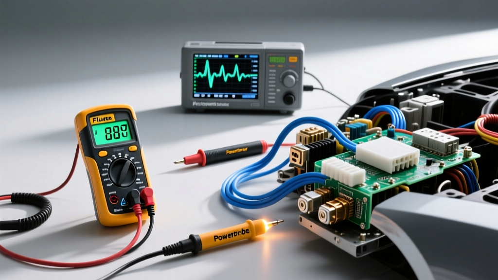
The Evolution of Car Electrical System Diagnosis
Modern vehicles are rolling data centers. With multiplexed networks like CAN, LIN, and FlexRay governing everything from fuel injection to adaptive cruise control, traditional test lights are not just inadequate—they are dangerous. Applying a low-impedance test light to a 5V reference circuit or a CAN bus line can instantly fry an Engine Control Module (ECM). Accurate car electrical system diagnosis demands specialized tools that match the impedance, sampling rate, and logic requirements of modern automotive architectures. In this selection guide, we compare the three pillars of automotive diagnostic hardware: the Digital Multimeter (DMM), the Logic Probe, and the Oscilloscope, specifically analyzing the industry-standard Fluke 88V, PowerProbe IV, and PicoScope 4425A.
Specification & Feature Comparison Matrix
| Feature / Specification | Fluke 88V (Automotive DMM) | PowerProbe IV (Logic Tester) | PicoScope 4425A (Oscilloscope) |
|---|---|---|---|
| Input Impedance | 10 MΩ (Standard) / 400 kΩ (LoZ) | Variable (Active Circuit Loading) | 1 MΩ ±1% (Selectable 50Ω) |
| CAT Rating | CAT III 1000V / CAT IV 600V | 12V/24V DC Systems Only | 200V Max (Differential BNC+) |
| Primary Diagnostic Strength | Voltage Drop, Parasitic Drain, Resistance | Relay Actuation, Power/Ground Verification | Network Comms, Sensor Waveforms, Transients |
| Risk to Solid State Electronics | Low (Safe for Airbag/SRS if rated) | High (If active output hits ECU drivers) | None (Passive High-Impedance Monitoring) |
Deep Dive: Fluke 88V Automotive Multimeter
The Fluke 88V remains the gold standard for high-current and precision low-current measurements. Its primary role in car electrical system diagnosis is voltage drop testing and parasitic drain isolation. Unlike measuring static voltage, voltage drop testing measures the difference in electrical pressure across a component or wire while under load, revealing hidden resistance.
Application: Starter Circuit Voltage Drop
Consider a slow-cranking 6.6L Duramax. A static battery test shows 12.6V, but the starter draws 400 amps. Using the Fluke 88V on the millivolt (mV) DC setting, place the red probe directly on the battery positive post (not the clamp) and the black probe on the starter solenoid B+ terminal. Crank the engine. According to Fluke's Automotive Voltage Drop Guidelines, a healthy 4 AWG or 1/0 AWG starter feed should exhibit less than 0.200V (200mV) of drop. A reading of 0.450V indicates high resistance, likely due to a corroded ring terminal or an undersized aftermarket battery cable.
Application: Parasitic Drain & CAN Bus Sleep
Modern vehicles require the CAN bus to "sleep" before measuring parasitic drain. On late-model FCA and GM vehicles, this sleep mode can take 20 to 45 minutes. The Fluke 88V’s 10A jack and optional i410 AC/DC current clamp allow you to monitor the drain without breaking the circuit (which would reset the ECU and wake the network). Target specification: under 50mA (0.050A) once all modules enter sleep state.
Deep Dive: PowerProbe IV Logic Tester
The PowerProbe IV excels at rapid power and ground verification and component actuation. It reads voltage, provides an audible tone for continuity, and can actively supply 12V or ground to a circuit. However, it requires strict discipline to avoid damaging sensitive electronics.
Application: Fuel Pump Relay Diagnostics
When diagnosing a dead fuel pump on a standard ISO 4-pin relay, the PowerProbe is unmatched. By back-probing the underhood fuse box relay socket:
Pin 85 (Ground): Verify continuity to chassis ground.
Pin 86 (Ignition 12V): Verify 12V with key ON.
Pin 30 (Constant 12V): Verify battery feed.
Pin 87 (Load to Pump): Use the PowerProbe’s active 12V output to energize Pin 87 directly. If the pump hums, the wiring to the tank is intact, and the fault lies in the relay or the PCM ground driver.
The Danger Zone: ECU Drivers
Never use the PowerProbe’s active 12V output on a circuit controlled by an ECM internal ground driver (such as fuel injector control wires or solenoid shift valves). The ECM uses low-side drivers rated for specific amperages; forcing 12V backward through a pintle or solenoid can instantly short the internal transistor, requiring a $1,200 ECM replacement.
Deep Dive: PicoScope 4425A Oscilloscope
When a multimeter's 10-megohm impedance and 2-readings-per-second refresh rate aren't fast enough to catch a microsecond glitch, the oscilloscope is mandatory. The PicoScope 4425A with BNC+ test leads is the definitive tool for network communication and transient sensor analysis.
Application: CAN Bus Decoding & Fault Finding
Per the SAE J1962 OBD-II Standard, the Data Link Connector (DLC) Pin 6 is CAN High and Pin 14 is CAN Low. Using the PicoScope, connect Channel A to Pin 6 and Channel B to Pin 14. A healthy High-Speed CAN network will show CAN High resting at 2.5V and spiking to 3.5V, while CAN Low rests at 2.5V and drops to 1.5V. If you see both lines mirroring each other, or if CAN High is pulled to 12V, you have identified a short-to-power or a shorted-wires fault that a DMM could only guess at.
Application: Injector Pintle Bump Analysis
Using a low-amp current clamp on the 18 AWG injector control wire, the PicoScope can graph the exact mechanical movement of the injector pintle. The initial inductive spike represents the ECM opening the circuit, while the secondary "pintle bump" (a small voltage rise a few milliseconds later) confirms the physical hydraulic movement of the needle. A missing pintle bump indicates a mechanically stuck injector, even if the electrical circuit is perfect.
Symptom-to-Tool Decision Tree
Selecting the right tool for the specific fault saves hours of diagnostic time. Use this matrix to guide your bench setup:
- Symptom: Intermittent Stalling / Random Misfire Codes
Tool: PicoScope. Why: You need to capture crank/cam sensor correlation waveforms over a 10-second cranking event to spot a dropped tooth or a failing Hall-effect sensor dropping out under heat. - Symptom: Battery Dead Every Morning
Tool: Fluke 88V. Why: You need high-resolution milliamp tracking over a 45-minute window to isolate which CAN module is failing to enter sleep mode. - Symptom: A/C Compressor Clutch Not Engaging
Tool: PowerProbe IV. Why: You can instantly verify the 12V feed at the clutch connector and use the active ground feature to bypass the vehicle's high-pressure safety switch wiring to verify the clutch coil mechanically.
Crucial Technique: Connector Back-Probing Best Practices
No matter which tool you select for your car electrical system diagnosis, how you interface with the wiring harness is critical. Modern vehicles utilize sealed connectors like the Molex MX150 and TE Deutsch DT series. Standard DMM probe tips (1.5mm) are too thick and will permanently spread the female terminal tines, causing a "no-contact" fault later.
Always use dedicated back-probing pins (0.64mm or 0.40mm). For waterproof Deutsch DT connectors, never pierce the silicone wire seals; moisture will wick into the copper strands via capillary action, causing green corrosion deep inside the harness. Instead, use flexible T-pins to gently slide past the rear seal retainer, making contact with the terminal barrel without compromising the weatherpack integrity. For in-depth network waveform capture, refer to Pico Technology's CAN Bus Training Library for proper differential probing techniques that avoid ground-loop interference.
Final Verdict
A master technician's cart requires all three technologies. The Fluke 88V validates the physical integrity of the copper (voltage drop). The PowerProbe IV verifies the logic and routing of power distribution networks. The PicoScope visualizes the invisible data and transient physics of the vehicle's sensors. Mastering the specific applications of each tool transforms car electrical system diagnosis from a frustrating guessing game into a precise, data-driven science.