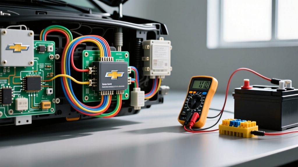
Introduction to Tahoe Electrical Architecture
The Chevrolet Tahoe, particularly across the GMT900 (2007-2014) and K2XX (2015-2020) platforms, relies on a highly multiplexed electrical architecture. At the heart of this system is the Body Control Module (BCM), which communicates via GMLAN (Global Manufacturer Local Area Network) and high-speed CAN bus networks. When owners report 'Chevrolet Tahoe electrical problems,' the root cause is rarely a failed module right out of the box. Instead, the culprits are usually compromised ground nodes, parasitic draws preventing module sleep, or water intrusion in junction blocks.
According to diagnostic frameworks outlined by the International Automotive Technicians Network (iATN), systematic fault-finding is mandatory. Throwing parts at a Tahoe with erratic gauges or a dead battery will drain your wallet. Follow this step-by-step troubleshooting flow to isolate and repair the most common Tahoe electrical gremlins.
Phase 1: Baseline Power & AC Ripple Verification
Before diagnosing complex network faults, you must verify the integrity of the primary power supply. The Tahoe's BCM and instrument cluster are highly sensitive to voltage fluctuations and electromagnetic interference (EMI), as outlined in SAE J1113 Electromagnetic Compatibility Standards.
Step 1.1: Static Voltage & Load Test
- Connect a Digital Multimeter (DMM) to the battery posts (not the clamps).
- Verify resting voltage is above 12.4V (approx. 75% state of charge).
- Perform a conductance load test. A weak cell can cause voltage to drop below 9.6V during cranking, triggering low-voltage DTCs (e.g., U0100, U0140) across multiple modules.
Step 1.2: Alternator AC Ripple Test
A failing alternator diode triode introduces AC voltage into the DC system. This 'noise' scrambles GMLAN data packets, causing the gauge cluster to reset or the HVAC blower to surge.
- Set your DMM to AC Volts (mV scale).
- Place the leads directly on the battery positive and negative posts.
- Start the engine and raise RPM to 2,000.
- Turn on the headlights and rear defroster to load the system.
- Specification: AC ripple must be less than 50mV (0.050V). If you read 200mV or higher, replace the alternator and retest before proceeding.
Phase 2: The Infamous G200 Ground & Voltage Drop Testing
If your Tahoe exhibits erratic HVAC blower behavior, dead instrument clusters, or seat memory faults, the G200 ground is your prime suspect. The G200 is the primary logic ground for the BCM and HVAC control modules.
Locating and Inspecting G200
The G200 ground node is located under the driver's seat, attached to the left-side floor pan sill. It typically consists of a 10 AWG Black wire with a ring terminal. Due to its location, it is highly susceptible to corrosion from wet shoes, spilled liquids, and condensation.
Step 2.1: Performing the Voltage Drop Test
Do not rely on a visual inspection or a simple continuity test. You must test the circuit under load.
- Set the DMM to DC Volts.
- Connect the Red probe to the Negative battery post.
- Connect the Black probe to the bare metal stud or ring terminal of the G200 ground.
- Turn the ignition ON and activate the HVAC blower to high speed (creating a heavy logic and accessory load).
- Specification: Maximum acceptable voltage drop is 0.10V (100mV). A reading of 0.25V or higher indicates high resistance.
Step 2.2: The Repair Procedure
If the G200 fails the voltage drop test, cut the corroded ring terminal off. Strip the 10 AWG Black wire, crimp a new adhesive-lined ring terminal, and apply heat shrink to seal out moisture. Reattach to the floor pan using a new M8 serrated flange nut. Torque specification: 9 Nm (80 lb-in). Ensure all paint and rust is scraped away from the mating surface to ensure bare metal-to-metal contact.
Phase 3: Critical Ground Nodes Reference Chart
Use this reference table when tracing ground-related faults across the Tahoe platform. Reference Haynes Automotive Electrical Troubleshooting Guides for full chassis wiring schematics.
| Ground ID | Location | Primary Systems Served | Wire Gauge / Color | Common Failure Symptom |
|---|---|---|---|---|
| G103 | Engine Block, Left Rear | ECM, Fuel Injectors, Ignition Coils | 8 AWG Black | Hard start, random misfires, P0300 codes |
| G200 | Under Driver Seat, Left Sill | BCM, HVAC Logic, Seat Memory | 10 AWG Black | Erratic blower motor, dead cluster, U-codes |
| G300 | Right Rear Quarter Panel | Rear HVAC, Liftgate Module, Audio Amp | 12 AWG Black/White | Rear blower inoperative, liftgate won't open |
| G400 | Center Console / Dash Cross-car | Radio, Navigation, OnStar Module | 14 AWG Black | Radio rebooting, OnStar connection failures |
Phase 4: Parasitic Draw Isolation & BCM Sleep Mode
A dead battery in the morning is a classic Tahoe complaint. The GMT900 and K2XX platforms feature multiple modules that must 'go to sleep' after the ignition is turned off. This sleep process can take up to 20 minutes. If a module stays awake, it will drain the battery.
Step 4.1: Setting Up the Ammeter
- Disconnect the negative battery cable.
- Set your DMM to the 10A DC setting.
- Connect the DMM in series between the negative battery post and the disconnected negative cable clamp.
- Wait 20-30 minutes for the BCM and GMLAN network to enter sleep mode.
- Specification: Normal parasitic draw must be below 50mA (0.050A).
Step 4.2: Isolating the Draw
If the draw remains high (e.g., 1.5A to 3.0A), suspect a stuck RAP (Retained Accessory Power) relay or a faulty window switch keeping the BCM awake. Begin pulling fuses in the interior instrument panel fuse block one by one. When the draw drops below 50mA, note the fuse circuit and consult the wiring diagram for components on that specific branch.
Phase 5: X50A Junction Block & Water Intrusion
The X50A Underhood Bussed Electrical Center (UBEC), located on the driver's side rear of the engine compartment, is notorious for water intrusion. The hood-to-cowl weather seal degrades over time, allowing rainwater to drip directly onto the X50A connector interface.
Diagnostic Steps for X50A
- Unlatch the X50A junction block and disconnect the lower harness connectors.
- Inspect the cavity for green/white copper oxide corrosion, specifically on the 14 AWG Pink (Ignition) and 10 AWG Orange (Battery Positive) circuits.
- Corrosion here increases resistance, leading to voltage drops that mimic a failing ignition switch or a bad BCM.
- Fix: Clean pins with electrical contact cleaner and a fiberglass pen. Replace the cowl seal and apply dielectric grease to the connector cavities to prevent future moisture ingress.
Phase 6: CAN Bus Network Diagnostics at the DLC
If your scan tool will not communicate with the Tahoe, or if you are pulling multiple 'U-codes' (Loss of Communication), you must verify the physical layer of the CAN bus network at the OBD2 Data Link Connector (DLC).
Step 6.1: Pinout & Voltage Verification
The high-speed CAN bus utilizes a twisted pair of 22 AWG wires. At the DLC, these map to specific pins:
- Pin 6 (CAN High): Resting voltage approx. 2.5V. Active voltage oscillates between 2.5V and 3.5V.
- Pin 14 (CAN Low): Resting voltage approx. 2.5V. Active voltage oscillates between 1.5V and 2.5V.
Step 6.2: Resistance Check (Network Termination)
- Turn the ignition OFF and disconnect the battery negative to prevent module back-feeding.
- Set the DMM to Ohms.
- Measure resistance between DLC Pin 6 and Pin 14.
- Specification: You should read exactly 60 Ohms. This confirms that the two 120-ohm terminating resistors (usually located inside the ECM and the BCM or gateway module) are in parallel and the network wiring is intact.
- If you read 120 Ohms, one terminating resistor or a main network trunk wire is open. If you read near 0 Ohms, the CAN H and CAN L wires are shorted together.
Tahoe Electrical Troubleshooting Decision Tree
Use this quick-reference logic flow to narrow down your diagnostic path:
- Symptom: Gauge Cluster Resets While Driving
- Check Alternator AC Ripple (Phase 1).
- If Ripple > 50mV -> Replace Alternator.
- If Ripple OK -> Check G200 Ground Voltage Drop (Phase 2).
- Symptom: Battery Dead Every Morning
- Perform Parasitic Draw Test (Phase 4).
- If Draw > 50mA after 20 mins -> Pull RAP Relay.
- If Draw Drops -> Replace Ignition Switch or Window Master Switch.
- Symptom: Scan Tool Won't Communicate / Multiple U-Codes
- Check DLC Pin 6 & 14 Resistance (Phase 6).
- If 120 Ohms -> Check for open splice pack or corroded X50A UBEC (Phase 5).
- If 0 Ohms -> Locate short to ground or short between CAN H/CAN L twisted pair.
Conclusion
Resolving Chevrolet Tahoe electrical problems requires moving beyond simple code reading and embracing systematic circuit testing. By validating power quality, performing rigorous voltage drop tests on critical nodes like G200, and understanding the nuances of GMLAN sleep modes and CAN bus termination, you can accurately diagnose and permanently repair the most stubborn electrical faults in these platforms.