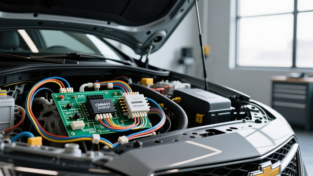
Introduction: The Hidden Dangers of Malibu Diagnostics
When diagnosing Chevy Malibu electrical problems, technicians and DIY enthusiasts often focus entirely on the symptom while ignoring the critical safety protocols required for modern GM Delta II and Global B architectures. The 8th and 9th generation Malibu models rely heavily on high-speed GMLAN networks, precision Battery Management Systems (BMS), and sensitive Supplemental Inflatable Restraint (SIR) circuits. A single diagnostic mistake can brick a Body Control Module (BCM), deploy an airbag, or cause a catastrophic thermal event. This guide outlines the most dangerous common mistakes and safety warnings you must heed before connecting a multimeter to any Malibu wiring harness.
Hazard 1: Battery Management System (BMS) Sensor Destruction
The negative battery terminal on modern Malibu models is not just a grounding post; it houses a precision Hall-effect Battery Current Sensor. This 3-pin connector monitors the exact amperage flowing in and out of the Absorbent Glass Mat (AGM) battery. The connector features an 18 AWG Red/White wire for the 12V reference, an 18 AWG Black wire for chassis ground, and a 20 AWG Purple/White wire carrying the Local Interconnect Network (LIN) bus signal back to the BCM.
The Fatal Mistake: Direct Negative Post Clamping
The most common mistake causing severe Chevy Malibu electrical problems is connecting a battery charger or jumper cable negative clamp directly onto the lead battery post. When you bypass the BMS shunt, the high-amperage inrush current arcs across the Hall-effect sensor, instantly melting the internal circuitry. Once the BMS is destroyed, the BCM loses its ability to monitor the battery state of charge (SOC). The alternator will default to a base voltage of 13.9V or spike to 15.5V, rapidly boiling the AGM electrolyte and destroying the battery within weeks.
Correct Protocol: Always connect negative charger clamps to the dedicated chassis ground stud on the left strut tower, never the battery post. If the BMS is suspected to be faulty, it must be replaced and recalibrated using a bidirectional scan tool to reset the SOC to 100%.
Hazard 2: X2 Connector and CAN Bus Backprobing Shorts
The Malibu’s Body Control Module (BCM) relies on high-speed GMLAN communication to talk to the Engine Control Module (ECM) and transmission. The CAN High (Dark Blue/White, 20 AWG) and CAN Low (Dark Blue, 20 AWG) circuits operate on a differential signaling protocol, typically hovering around 2.5V at idle.
The Fatal Mistake: Terminal Spreading and Bus Shorting
Backprobing the OBD-II Data Link Connector (DLC) or the BCM X2 connector with standard, thick multimeter probes is a catastrophic error. The female terminals in the X2 connector are designed for a specific pin retention tension. Forcing a standard test probe into Pin 6 (CAN High) or Pin 14 (CAN Low) permanently spreads the terminal. This creates an intermittent high-resistance connection that triggers U0100 (Lost Communication with ECM) or U0140 (Lost Communication with BCM) codes that are nearly impossible to replicate in the bay.
Furthermore, if your probe slips and shorts the 20 AWG CAN Low wire to the adjacent 18 AWG 12V power circuit, you will instantly fry the CAN transceivers in every module on that bus network, resulting in thousands of dollars in module replacements.
Correct Protocol: Always use dedicated, ultra-thin backprobing pins or T-pin adapters specifically designed for GM micro-pack terminals. Never use test lights on CAN bus circuits; the incandescent bulb's current draw will collapse the network voltage and set false U-codes.
Hazard 3: Supplemental Inflatable Restraint (SIR) System Probing
The Malibu’s SIR system, encompassing airbags, seatbelt pretensioners, and side-impact sensors, is identifiable by its bright yellow outer loom and yellow 2-pin to 4-pin connectors.
The Fatal Mistake: DMM Voltage Injection
Using a standard Digital Multimeter (DMM) to test continuity or voltage on a yellow SIR harness is life-threatening. Standard DMMs output between 3V and 9V from their internal batteries when performing continuity or resistance checks. Modern pyrotechnic squibs in Malibu steering wheels and seat-mounted thorax bags can deploy with as little as 1.5V to 3V of applied energy if the internal shunt is compromised or if the probe bypasses the shorting bars inside the connector. Deploying an airbag in your face while leaning over the steering column is a severe safety hazard.
Correct Protocol: Never pierce or backprobe a yellow wire. If an SIR Diagnostic Trouble Code (DTC) such as B0012 or B0013 is present, you must use a specialized low-energy SIR tester, such as the GM EL-50330 equivalent, which limits current output to micro-amps. Always disconnect the negative battery cable and wait a minimum of 60 seconds for the backup energy reserve capacitors in the Sensing and Diagnostic Module (SDM) to discharge before touching any yellow connector.
Hazard 4: Ground Point G103 Corrosion and Improper Torque
Ground G103, located on the left front strut tower, is a primary grounding point for the ABS module, headlamp control modules, and the BMS. It utilizes a 6mm stud and an 8 AWG bare copper ground cable.
The Fatal Mistake: Impact Gun Stripping and Galvanic Trapping
When cleaning G103 to resolve voltage drop issues, many mechanics use a wire wheel on a high-speed die grinder, which removes the factory-applied conductive zinc coating and exposes raw aluminum. When reassembling, using a pneumatic impact gun often strips the soft aluminum threads of the strut tower. This results in a loose ground that causes headlamp flickering and ABS module communication dropouts over bumps.
Correct Protocol: Clean G103 using only a brass-bristle brush and electrical contact cleaner. Apply a thin layer of dielectric grease to the outside edges to prevent moisture ingress, but keep it away from the mating surfaces. Torque the 6mm nut to exactly 10 Nm (89 lb-in) using a calibrated inch-pound torque wrench.
Hazard 5: Parasitic Drain and the Retained Accessory Power (RAP) Trap
The Malibu's BCM controls the Retained Accessory Power (RAP) circuit, which keeps accessories like the radio and windows powered for 10 minutes after the ignition is turned off. This is fed via Pin 4 on the X5 BCM connector (Brown wire, 14 AWG).
The Fatal Mistake: Aftermarket Dashcam Tapping
Tapping into the RAP circuit for aftermarket dashcams or GPS trackers without a proper low-quiescent-current relay or hardwire kit with low-voltage cutoff is a massive mistake. Even a 30mA parasitic drain will prevent the BCM from entering its deep sleep mode. The BCM will continuously attempt to poll the GMLAN network, resulting in a dead battery within 72 hours.
Correct Protocol: Always use an add-a-fuse on a non-critical, ignition-switched circuit in the underhood fuse block, paired with a dedicated voltage-sensing relay that physically disconnects the accessory when battery voltage drops below 11.8V.
Technical Reference: Malibu BCM & BMS Pinout Safety Chart
| Circuit / Component | Wire Color | AWG | Pin / Location | Critical Safety Warning |
|---|---|---|---|---|
| BMS LIN Bus | Purple/White | 20 | BMS Connector Pin 3 | Do not backprobe; high sensitivity to capacitance and static |
| CAN High (GMLAN) | Dark Blue/White | 20 | OBD-II DLC Pin 6 | Spreading terminal causes intermittent U0100 network drops |
| CAN Low (GMLAN) | Dark Blue | 20 | OBD-II DLC Pin 14 | Never short to ground; instantly disables high-speed bus |
| SIR Driver Squib | Yellow | 18 | Steering Wheel Conn. | DMM voltage injection can cause catastrophic deployment |
| G103 Chassis Ground | Bare Copper | 8 | Left Strut Tower | Torque to 10 Nm; impact guns strip aluminum threads |
| RAP Relay Feed | Brown | 14 | BCM X5 Conn. Pin 4 | Aftermarket taps cause BCM sleep-mode failure and drain |
Conclusion & PPE Requirements
Diagnosing Chevy Malibu electrical problems requires a methodical, safety-first approach that respects the engineering tolerances of modern automotive networks. By avoiding brute-force probing, respecting the BMS charging architecture, and treating the SIR system with the caution it demands, you protect both yourself and the vehicle's delicate electronics. Always consult factory wiring diagrams, verify your tool's output specifications, and adhere strictly to GM's torque and terminal-tension guidelines. For further reading on GM network topologies and safety standards, refer to resources provided by GM TechLink, NHTSA Airbag Safety Guidelines, and SAE International J2284 high-speed CAN standards.