The Hidden Cost of Aftermarket Upgrades: Ground Loops and Voltage Drops
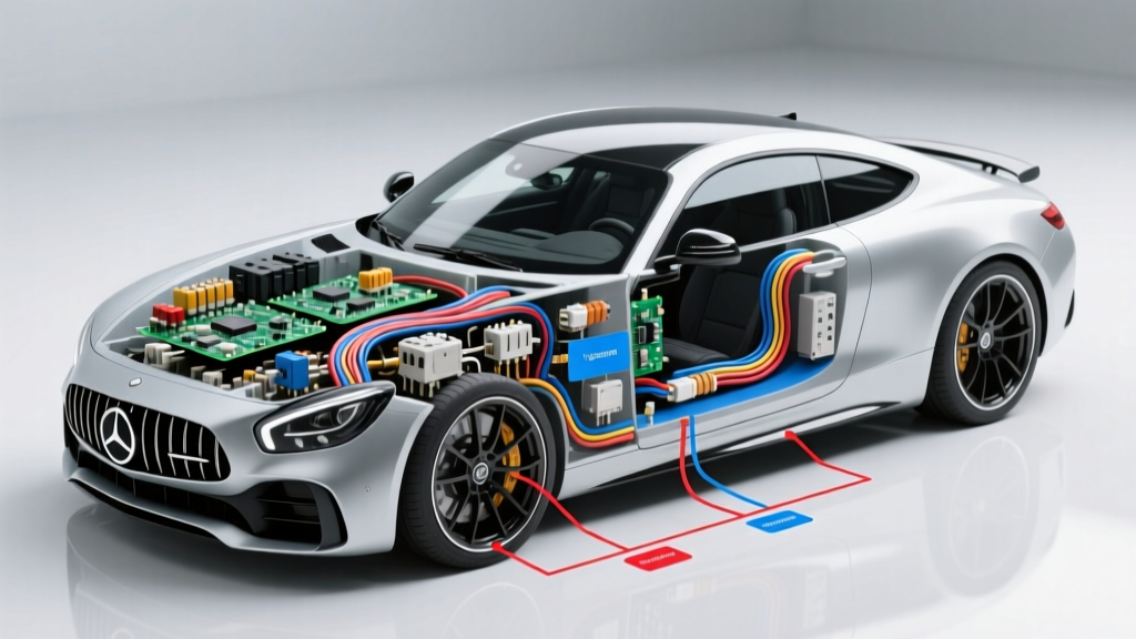
When you bolt on a 12,000-lb winch, a 2,000-watt audio amplifier, or a 50-inch LED light bar, you are fundamentally altering the vehicle's electrical architecture. Factory wiring harnesses are engineered with a strict 10-15% overhead margin. Exceeding this margin inevitably leads to severe electrical problems that can range from annoying alternator whine to catastrophic ECU failure. Most enthusiasts assume that simply wiring a new accessory directly to the battery with an inline fuse is sufficient. However, ignoring the baseline charging system capacity and chassis grounding points is the primary cause of modification-induced electrical problems.
This guide provides a systematic, expert-level approach to diagnosing and resolving electrical problems that arise specifically after high-amp accessory installations. We will cover voltage drop testing, ground loop isolation, and the critical 'Big Three' wiring upgrade necessary to support modern aftermarket modifications.
Symptom-to-Root-Cause Decision Matrix
Before grabbing a multimeter, identify the specific behavior of your electrical problems. Use this matrix to pinpoint the likely failure point in your modified circuit.
| Symptom | Probable Root Cause | Diagnostic Focus Area |
|---|---|---|
| Alternator whine in audio system that pitches up/down with RPM | Ground loop or RCA shield interference | Amplifier chassis ground vs. head unit ground potential difference |
| Headlights dim heavily when winch or cooling fans engage | Insufficient alternator output or high-resistance main positive cable | Alternator B+ terminal to battery positive voltage drop under load |
| ECU throws phantom codes (P0562 System Voltage Low, P0563 High) | Dirty power or voltage spike from improper relay flyback diode suppression | Relay harness pins 85/86, ECU main power relay feed |
| High-draw accessory cuts out intermittently under heavy load | Thermal shutdown due to undersized wire gauge or poor crimp termination | Wire temperature, inline fuse holder terminal tension, crimp pull-test |
Executing the 'Big Three' Wiring Upgrade
If your electrical problems involve system-wide dimming or ECU brownouts during accessory use, your factory grounding and charging straps are bottlenecking the current. The 'Big Three' upgrade replaces the three most critical factory cables with 1/0 AWG (or 4 AWG for moderate builds) SAE J1128 GXL cross-linked polyethylene wire, which is rated for continuous 125°C operation.
- Alternator Positive to Battery Positive: Factory wiring often routes through a 120A fusible link and undersized 6 AWG wire. Replace this with 1/0 AWG flexible welding cable and an ANL fuse rated 150% of the alternator's maximum output.
- Engine Block to Chassis Ground: Engine movement fatigues factory braided straps. Install a dedicated 1/0 AWG ground strap from a clean, bare-metal point on the engine block (avoid exhaust manifolds) to a structural chassis point. Torque the M8 or M10 grounding bolts to 18-22 Nm using a star washer to bite through any microscopic corrosion.
- Battery Negative to Chassis Ground: This completes the circuit for all chassis-grounded accessories. Ensure the ring terminal is crimped with a hex-crimp die, not an indent crimper, to ensure maximum copper strand compression and minimal electrical resistance.
For deeper insights into OEM vs. aftermarket cable specifications, refer to the SAE J1128 Low Tension Primary Cable Standard, which dictates the strand count, insulation thickness, and thermal ratings required for automotive environments.
Voltage Drop Testing the Modified Circuit
When troubleshooting electrical problems in a newly installed high-amp circuit (like an off-road light bar relay harness), resistance is your enemy. A multimeter reading of 12.6V at the battery means nothing if the relay pin 30 is only receiving 10.5V under load. You must perform a dynamic voltage drop test.
Step-by-Step Voltage Drop Procedure
- Set your digital multimeter (DMM) to DC Volts (20V range).
- Turn ON the high-draw accessory to place the circuit under maximum load.
- Positive Side Test: Place the red probe on the battery positive post and the black probe on the accessory's positive input terminal. A reading above 0.5V indicates excessive resistance in the power feed (undersized wire, corroded fuse holder, or poor relay pin 87 connection).
- Negative Side Test: Place the red probe on the accessory's negative terminal and the black probe on the battery negative post. A reading above 0.2V indicates a faulty ground connection.
- Connection Isolation: Move probe-to-probe across each individual connection (e.g., across the fuse, across the relay terminals). Each individual mechanical connection should drop no more than 0.1V.
According to Painless Performance Wiring Manuals, a voltage drop exceeding 3% of the system voltage (approx. 0.4V on a 13.8V charging system) will significantly reduce the lumen output of lighting upgrades and cause severe thermal buildup in DC motors like winches and fuel pumps.
Wire Gauge and Overcurrent Protection Chart
Selecting the incorrect wire gauge is a leading cause of electrical problems, resulting in melted insulation or catastrophic short circuits. Never size your fuse based on the accessory's draw; size the fuse to protect the wire. Use the chart below for 12V-14V automotive DC systems, assuming a maximum wire run of 15 feet (round trip).
| Wire Gauge (AWG) | Max Continuous Current | Recommended Fuse Type | Max Fuse Rating | Typical Application |
|---|---|---|---|---|
| 1/0 AWG | 150A - 200A | ANL or Class-T | 250A | Main battery feeds, Big Three, massive inverters |
| 4 AWG | 100A - 120A | ANL or Mega | 150A | High-power audio amplifiers, 12,000-lb winches |
| 8 AWG | 50A - 60A | Maxi or ANL | 70A | 50-inch LED light bars, auxiliary fuse blocks |
| 10 AWG | 30A - 40A | Maxi or ATO | 40A | Off-road driving lights, air compressors |
| 12 AWG | 20A | ATO/ATC Blade | 20A | Relay trigger circuits, horn upgrades, fuel pumps |
Proper Grounding and Termination Standards
Over 80% of aftermarket electrical problems trace back to improper grounding techniques. Painting over a ground strap, using self-tapping screws into thin sheet metal, or relying on rust-prone steel ring terminals will guarantee future failures.
The Perfect Ground Point
- Surface Preparation: Use a 3M Roloc bristle disc or sandpaper to remove all paint, powder coat, and primer down to bare, shiny steel or aluminum. The contact area must be slightly larger than the ring terminal footprint.
- Hardware Selection: Use a Grade 8 or stainless steel bolt with a hardened flat washer and a star (external tooth) lock washer. The star washer must sit between the flat washer and the ring terminal to bite into the copper and prevent vibration loosening.
- Corrosion Protection: Once torqued to spec (typically 18-22 Nm for an M8 bolt into a captive nut), coat the entire terminal and exposed bare metal with a heavy layer of dielectric grease or marine-grade anti-corrosion compound. Never apply the grease before tightening, as it acts as an insulator and increases contact resistance.
- Galvanic Corrosion Warning: If grounding to an aluminum chassis component (common in modern unibody vehicles), you must use a specialized bi-metallic lug or apply a heavy coat of anti-oxidant paste (like Noalox) to prevent galvanic corrosion between the copper terminal and aluminum chassis.
Relay Harnesses and Flyback Diode Suppression
When modifying circuits to trigger high-amp loads via the factory ECU or body control module (BCM), you must use a relay. Standard ISO mini relays utilize pins 85 and 86 for the coil, pin 30 for constant 12V power, and pin 87 for the switched output. When the ECU drops the ground on pin 86 to turn off the relay, the collapsing magnetic field in the coil generates a high-voltage reverse spike (flyback voltage). If your upgraded harness lacks an integrated flyback suppression diode across pins 85 and 86, this spike will feed back into the ECU driver transistor, eventually causing expensive module failure.
Always verify that aftermarket relay harnesses include a reverse-polarity protection diode. If building a custom harness, solder a 1N4004 diode across the coil pins, with the cathode stripe facing the positive 12V trigger source. For comprehensive diagnostic procedures and wiring schematics, consult MOTOR Information Systems to ensure your modifications align with OEM CAN-bus and BCM tolerances.
Summary
Upgrading your vehicle with high-draw accessories requires a holistic view of the entire electrical ecosystem. By executing the Big Three upgrade, strictly adhering to SAE wire gauge standards, performing dynamic voltage drop tests, and utilizing proper termination hardware, you can permanently eliminate the electrical problems that plague amateur modification projects. Treat every connection as a potential point of failure, and test under load before finalizing your wire routing.