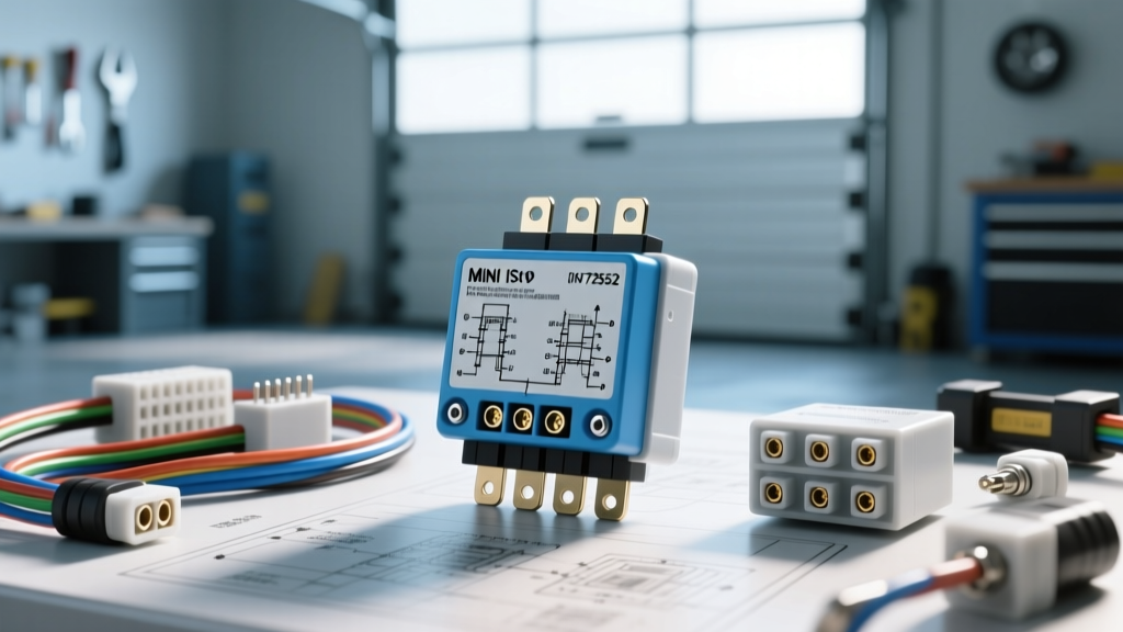
Why You Must Properly Extract and Upgrade Your Relays
When an automotive lighting circuit fails—whether it is a high-draw LED light bar, a halogen headlight upgrade, or a factory fog light system—the electromagnetic relay is the most common point of failure. Relays act as the heavy-duty switch that isolates high-amperage load circuits from low-amperage switch circuits. Over time, the internal contacts can pit, arc, or weld together, causing intermittent operation or total failure. Understanding exactly how to remove a car relay without damaging the delicate fuse box terminals is only the first step. Once extracted, you must select the correct replacement. This guide bridges the gap between safe extraction procedures and a comprehensive product comparison of OEM versus aftermarket Mini ISO relays, ensuring your lighting system receives reliable, high-current power.
Step-by-Step: How to Remove a Car Relay Safely
Modern vehicles utilize centralized power distribution centers (PDCs) or instrument panel (IP) fuse blocks, often manufactured by Delphi or Yazaki. These housings secure the relays using stiff locking tabs to prevent them from vibrating loose. Forcing a relay out without disengaging these tabs will crack the PDC housing or cause terminal back-out inside the connector.
1. Isolate the Power Source
Always disconnect the negative battery terminal before working inside a PDC. While the coil side of the relay (Pins 85 and 86) operates on low current, the load side (Pin 30) is often fed directly from the battery via a high-amperage maxi-fuse. Shorting Pin 30 to ground with a metal tool during extraction can cause severe arcing and melt the internal bus bars of the fuse box.
2. Disengage the Locking Mechanism
Inspect the base of the relay. Most Mini ISO relays feature a small plastic retention clip on one or two sides. Use a plastic trim removal tool or a specialized relay puller with a hooked end to depress the locking tab. Never use metal needle-nose pliers to pry the relay, as slipping will gouge the PDC cover and damage adjacent fuses.
3. The Extraction Technique
Grip the relay body firmly and pull straight upward while simultaneously rocking it side-to-side by no more than two degrees. Never pull on the wiring harness. Pulling on the wires will extract the female Delphi Metri-Pack 280 series terminals from their cavities, requiring a specialized terminal release tool to reseat them. If the relay is seized due to heat warping, spray a small amount of electrical contact cleaner around the base to lubricate the rubber sealing ring, wait three minutes, and try again.
Bench Testing the Extracted Relay (DIN 72552 Standard)
Before purchasing a replacement, verify the extracted relay is actually faulty. Automotive relays follow the DIN 72552 standard for terminal numbering. Using a digital multimeter (DMM), perform the following tests:
- Coil Resistance (Pins 85 & 86): Set your DMM to Ohms. Place probes on 85 and 86. A healthy 12V coil should read between 50 and 120 ohms. A reading of 'OL' (Open Loop) indicates a burned-out internal copper windings.
- Load Continuity (Pins 30 & 87): Set your DMM to Continuity. Place probes on 30 (Common/Power) and 87 (Normally Open). The meter should read 'OL'. If it beeps or shows near-zero resistance, the internal contacts have welded together due to high-amperage arcing.
- Active Switch Test: Apply 12V from a spare battery to Pins 85 and 86 (polarity does not matter unless a diode is present). You should hear a distinct click. Re-test Pins 30 and 87 for continuity; it should now read less than 0.1 ohms.
Product Comparison: Selecting the Best Replacement Relay
Once you know how to remove a car relay and have confirmed its failure, you must select a replacement. The market is flooded with options, but not all relays are engineered equally. When upgrading lighting systems, the internal contact material and coil specifications are critical.
OEM vs. Aftermarket Brands
Original Equipment Manufacturer (OEM) relays are typically produced by tier-one suppliers like Hella, Bosch, or OMRON. These are excellent for factory-spec replacements. However, when installing aftermarket lighting (like a 50-inch 300W LED light bar), you should look to specialized aftermarket electrical brands like Littelfuse or Standard Motor Products (SMP). These brands often offer heavy-duty variants with higher thermal tolerances and upgraded contact materials designed specifically for the high inrush currents of modern lighting.
Contact Material: AgNi vs. AgSnO2
Standard factory relays use Silver Nickel (AgNi) contacts. While fine for resistive loads like factory blower motors, AgNi contacts can suffer from severe pitting and material transfer when switching the high capacitive inrush currents of LED drivers or halogen bulbs. For lighting upgrades, always select a relay with Silver Tin Oxide (AgSnO2) contacts. AgSnO2 resists arc erosion, prevents contact welding, and vastly extends the lifespan of the relay under heavy lighting loads.
Form Factor: Micro ISO vs. Mini ISO
Ensure you match the physical footprint. Micro ISO relays (typically 20A, 12.5mm wide) are common in modern European vehicles for interior lighting and small modules. Mini ISO relays (typically 30A-40A, 25.4mm wide) are the standard for exterior lighting, radiator fans, and fuel pumps. Forcing a Micro ISO into a modified Mini ISO slot will result in loose terminal connections and localized melting.
Automotive Relay Specification & Selection Chart
| Relay Type | Form Factor | Max Continuous Load | Best Application |
|---|---|---|---|
| Standard Mini ISO (4-Pin) | 25.4mm x 25.4mm | 30A - 40A | Factory fog lights, horn, standard LED bars |
| Heavy-Duty Mini ISO (AgSnO2) | 25.4mm x 25.4mm | 40A - 50A | High-draw halogen headlight upgrades, winches |
| Micro ISO (4-Pin) | 12.5mm x 15.0mm | 15A - 20A | Interior LEDs, daytime running lights (DRL) |
| 5-Pin Changeover (Mini ISO) | 25.4mm x 25.4mm | 30A (NO) / 20A (NC) | Headlight high/low beam switching, polarity reversal |
| Maxi Relay | 30.0mm x 30.0mm | 50A - 70A | Radiator cooling fans, glow plugs, main power distribution |
Wiring Upgrades and Installation Best Practices
When installing your newly selected replacement relay, especially in custom lighting harnesses, adhering to SAE International wiring standards is paramount to prevent voltage drop and fire hazards.
- Wire Gauge Selection: The coil circuit (Pins 85 and 86) draws less than 200mA, so 18 AWG or 20 AWG wire is sufficient. However, the load circuit (Pins 30 and 87) must be sized for the amperage. For a 30A relay, use a minimum of 12 AWG wire. For a 40A relay, step up to 10 AWG wire to account for voltage drop over distance and engine bay heat.
- Wire Insulation Type: Avoid standard PVC primary wire (GPT) in the engine bay. Instead, use TXL (cross-linked polyethylene) wire. TXL features a thinner wall for easier routing through firewalls and grommets, and it withstands continuous temperatures up to 125°C without the insulation melting against the relay spades.
- Terminal Protection: Apply a small dab of dielectric grease to the male spade terminals of the relay before inserting it into the female Metri-Pack connectors. This prevents galvanic corrosion and moisture ingress, which are the leading causes of high-resistance voltage drops at the PDC.
- Suppression Diodes: If your lighting circuit is controlled by a sensitive ECU or a solid-state switch (like a modern PWM headlight switch), ensure your replacement relay features an internal suppression diode or resistor across Pins 85 and 86. This clamps the inductive voltage spike generated when the coil collapses, protecting your vehicle's delicate CAN-bus modules from back-EMF damage.
Real-World Failure Modes to Inspect During Removal
As you learn how to remove a car relay, take a moment to inspect the relay socket and the extracted unit for physical clues regarding the failure. If the plastic housing around Pin 30 or Pin 87 is discolored or melted, the relay was subjected to a load exceeding its amperage rating, or the female terminal in the harness has lost its spring tension, creating a high-resistance connection that generates severe heat. In this scenario, simply replacing the relay is not enough; you must use a terminal pick to extract the damaged female wire from the connector block and crimp on a new, gold-plated Delphi Metri-Pack 280 terminal. Ignoring a heat-damaged socket will cause your premium aftermarket replacement relay to fail prematurely, leaving your lighting system dead on the trail.