Decoding the Five Pin Relay Wiring Diagram: SPDT Logic
When upgrading automotive lighting systems, integrating off-road LED light bars, or managing complex accessory circuits, a standard 4-pin relay often falls short. This is where understanding a five pin relay wiring diagram becomes critical. Unlike its 4-pin counterpart (SPST - Single Pole Single Throw), the 5-pin relay operates as an SPDT (Single Pole Double Throw) switch. This allows a single trigger signal to toggle power between two separate output circuits, making it the cornerstone of advanced automotive electrical routing.
According to the DIN 72552 standard for automotive electrical terminals, the 5-pin relay utilizes specific numerical designations to ensure universal compatibility across harnesses:
- Pin 30 (Common): The main power input from the battery (typically fused).
- Pin 85 (Coil Ground): The ground path for the internal electromagnetic coil.
- Pin 86 (Coil Power): The switched 12V+ trigger signal (e.g., from a dashboard switch or ECU).
- Pin 87 (Normally Open - NO): Receives power only when the relay coil is energized.
- Pin 87a (Normally Closed - NC): Receives power when the relay is at rest, and cuts off when energized.
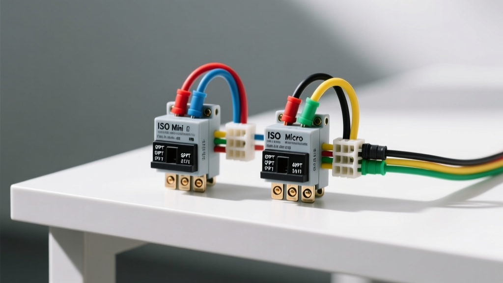
Product Comparison: ISO Mini vs. ISO Micro vs. Maxi Relays
Before executing your five pin relay wiring diagram, selecting the correct physical form factor and amperage rating is paramount. The automotive industry primarily relies on ISO-standardized relays, but their physical dimensions and terminal widths dictate their specific use cases. Referencing Littelfuse Automotive Relays and TE Connectivity guidelines, we can break down the three most common SPDT configurations.
| Specification | ISO Mini (280-Type) | ISO Micro (280-Micro) | ISO Maxi (High-Duty) |
|---|---|---|---|
| Terminal Width | 6.3mm (1/4 inch) | 2.8mm (0.110 inch) | 9.5mm (3/8 inch) |
| Continuous Current | 20A - 30A | 10A - 15A | 40A - 70A |
| Inrush Capacity | Up to 60A | Up to 30A | Up to 120A |
| Typical Application | Fog lights, fuel pumps, horn | ECU triggers, DRL modules, LEDs | Winches, massive light bars, starters |
| Connector Style | Packard/Amphenol 280 | Delphi/Molex Micro | Heavy-Duty Ring/Spade |
For most aftermarket lighting installations (such as 50W LED pods or halogen fog lights), the ISO Mini 30A/40A relay is the industry standard. However, if your five pin relay wiring diagram involves switching low-draw LED halos or sending a signal to an ECU, the ISO Micro prevents the need to step-down wire gauges at the socket.
Matching Wire Gauge (AWG) to Relay Amperage
A common failure point in DIY lighting installs is pairing a 40A relay with undersized wire, leading to voltage drop and melted insulation. When planning your circuit, you must adhere to SAE J1128 standards for automotive primary wire. Always use cross-linked polyethylene (XLPE) insulated wire, such as TXL (Thin-wall) or GXL (General), which withstands engine bay temperatures up to 125°C (257°F).
| Relay Rating (Max Load) | Recommended Wire Gauge (GXL/TXL) | Terminal Crimp Type | Inline Fuse Size |
|---|---|---|---|
| 10A - 15A (Micro) | 16 AWG | 2.8mm Open Barrel | 15A ATO/ATC |
| 20A - 30A (Mini) | 12 AWG (or 10 AWG for long runs) | 6.3mm Open Barrel | 25A or 30A ATO |
| 40A+ (Maxi) | 8 AWG (or 6 AWG) | Ring Terminal / 9.5mm | 40A or 50A Mega/ANL |
Expert Tip: Never use closed-barrel crimpers on modern Packard 280 weather-pack terminals. Use a dedicated open-barrel crimper to ensure the wire insulation crimp and conductor crimp are properly formed, preventing moisture intrusion and terminal pull-out.
Real-World Application: DRL Cutoff & Headlight Integration
The true power of the five pin relay wiring diagram lies in utilizing Pin 87a (Normally Closed). A classic application of this is the Daytime Running Light (DRL) to Headlight cutoff circuit, frequently used in custom Jeep, Tacoma, and Bronco builds.
Step-by-Step DRL Cutoff Wiring
- Pin 30: Connect to a fused 12V+ constant battery source (e.g., 10A fuse).
- Pin 86: Connect to the vehicle's headlight positive trigger wire (powers on when low beams are activated).
- Pin 85: Connect to a clean chassis ground.
- Pin 87a (Normally Closed): Connect to the positive input of your DRL lighting circuit.
- Pin 87 (Normally Open): Leave unused or cap it with a heat-shrink butt connector.
How it works: When the vehicle is running and headlights are OFF, the relay coil is de-energized. Power flows from Pin 30 to Pin 87a, illuminating the DRLs. The moment the driver turns on the low beams, Pin 86 receives 12V+, energizing the coil. The internal switch throws from 87a to 87, instantly cutting power to the DRLs while allowing the main headlights to operate. This prevents the blinding glare of DRLs mixing with low beams and satisfies DOT compliance requirements.
Protecting the Circuit: Flyback Diodes and Inductive Kickback
When the electromagnetic coil inside a 5-pin relay is suddenly deprived of power (e.g., turning off a dashboard switch), the collapsing magnetic field generates a high-voltage reverse spike known as inductive kickback. This spike can exceed 100V and will instantly fry sensitive solid-state switches, ECU driver circuits, or modern CAN-bus modules.
To prevent this, your five pin relay wiring diagram must include a flyback diode (such as a 1N4004 or 1N4007) wired in parallel across the coil pins (85 and 86).
- Wire the Cathode (the side with the silver stripe) to Pin 86 (12V+ Switched).
- Wire the Anode to Pin 85 (Ground).
This reverse-bias configuration ensures the diode blocks normal 12V operation. However, when the switch opens and the voltage spikes in reverse, the diode becomes forward-biased, creating a safe loop that dissipates the inductive energy back into the coil, protecting your vehicle's sensitive electronics. Many premium ISO Mini relays now come with internal diodes or resistors; always check the schematic printed on the relay casing before adding an external diode to avoid creating a dead short.
Troubleshooting Common 5-Pin Relay Failures
If your lighting circuit fails after following the diagram, use a digital multimeter (DMM) to diagnose these common issues:
- Symptom: Relay clicks, but no power at Pin 87 or 87a.
Cause: Voltage drop on the Pin 30 feed wire, or corroded 6.3mm spade terminals. Check for 12V+ at Pin 30 under load. - Symptom: Relay gets excessively hot and melts the harness.
Cause: Exceeding the continuous amperage rating. A 30A relay running a 45A light bar will overheat the internal copper windings. Upgrade to an ISO Maxi relay or use the 5-pin relay solely as a low-current trigger for a heavier secondary contactor. - Symptom: DRLs flicker when the engine cranks.
Cause: Voltage drop during starter engagement drops the system below the relay's 8V dropout threshold. Install a capacitor across the coil pins or wire Pin 86 to an ignition-run circuit rather than a crank-susceptible bus.
Mastering the five pin relay wiring diagram elevates your automotive electrical builds from amateur hacks to OEM-grade installations. By matching the correct ISO form factor to your amperage requirements, selecting the proper TXL/GXL wire gauge, and implementing inductive protection, you ensure your lighting and accessory systems operate flawlessly in the harshest environments.