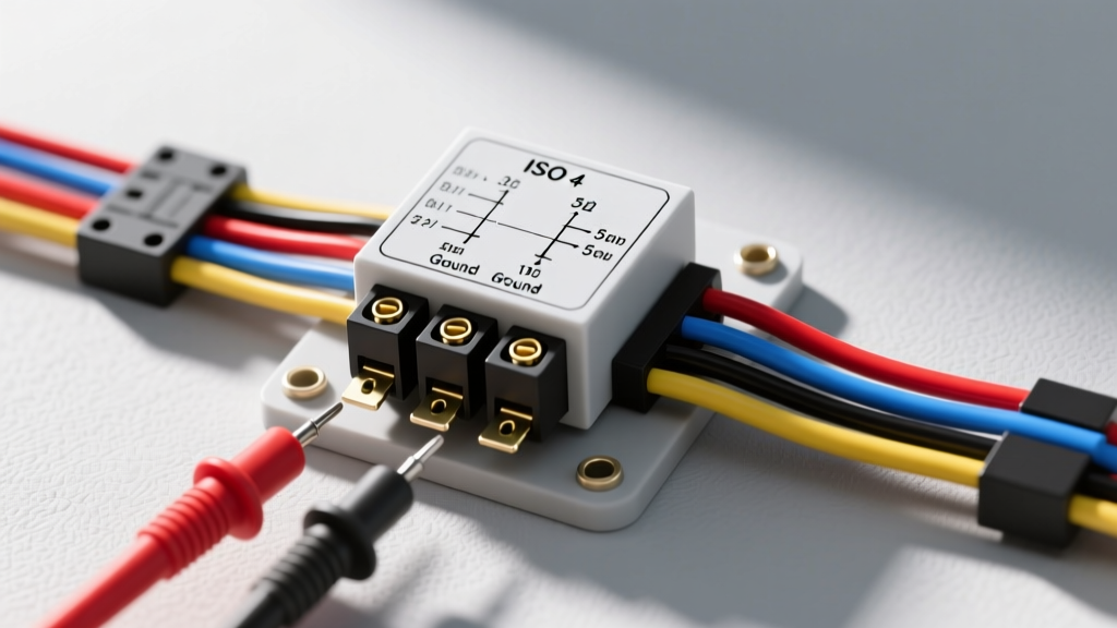
Automotive Relay Testing: Technical Specification Reference
When diagnosing lighting failures, fuel pump cutoffs, or accessory malfunctions, understanding how do you test a car relay is a fundamental diagnostic skill. An automotive relay is an electrically operated switch that uses a low-current control circuit to manage a high-current load circuit. Most modern vehicles utilize ISO 7588 standard mini or micro relays. Unlike simple fuse testing, relay diagnostics require a systematic approach to verify both the electromagnetic coil integrity and the mechanical switch contact resistance. This technical reference outlines the exact multimeter settings, DIN 72552 terminal pinouts, and voltage drop thresholds required to accurately bench-test 4-pin and 5-pin automotive relays.
Standard Pinout Configurations & Terminal IDs
Before applying a multimeter, you must identify the terminal numbers stamped on the relay casing or depicted on the internal schematic. The automotive industry follows the DIN 72552 standard for terminal numbering. According to MAD Electrical, misidentifying the control and load circuits is the most common cause of diagnostic errors and accidental harness shorts.
| Terminal ID | Circuit Type | Function (4-Pin) | Function (5-Pin) | Typical Wire Gauge (AWG) |
|---|---|---|---|---|
| 85 | Control (Coil) | Coil Ground / Trigger | Coil Ground / Trigger | 18 - 16 AWG |
| 86 | Control (Coil) | Coil 12V+ Supply | Coil 12V+ Supply | 18 - 16 AWG |
| 30 | Load (Switch) | Common Power Input | Common Power Input | 12 - 10 AWG |
| 87 | Load (Switch) | Normally Open (NO) Output | Normally Open (NO) Output | 12 - 10 AWG |
| 87a | Load (Switch) | N/A | Normally Closed (NC) Output | 12 - 10 AWG |
Required Testing Equipment & Setup
To perform a comprehensive relay analysis, you need a digital multimeter (DMM) capable of measuring resistance (Ohms), DC voltage, and continuity. Additionally, prepare a 12V power source (a fully charged vehicle battery or a regulated bench power supply set to 13.8V) and jumper wires. Crucial Specification: When constructing jumper wires for the load circuit (Pins 30 and 87), use a minimum of 14 AWG stranded copper wire. Using thin 18 AWG wire for high-amperage load testing will introduce artificial voltage drop and yield false-negative diagnostic results.
Phase 1: Testing the Electromagnetic Coil (Pins 85 & 86)
The coil is an electromagnet that pulls the internal armature to close the switch contacts. A failed coil will result in zero switching action.
Resistance Measurement
- Set your DMM to the Ohms (Ω) setting, typically the 200Ω range.
- Place the probes on terminals 85 and 86. Polarity does not matter for basic resistance testing.
- Pass Specification: A standard 12V automotive relay coil should read between 65Ω and 120Ω.
- Fail States: A reading of "OL" (Out of Limits) indicates an open internal winding. A reading below 10Ω indicates a shorted winding. Both require relay replacement.
Suppression Diode & Resistor Verification
Many modern OEM relays contain an internal suppression diode or resistor to prevent voltage spikes from damaging the ECU or BCM when the magnetic field collapses. If your relay has a diode, testing continuity in one direction may show "OL" while the reverse direction shows a standard reading. To verify a diode-protected relay, switch your DMM to the Diode Test setting. Probing in the forward bias direction should yield a voltage drop of approximately 0.5V to 0.7V. Probing in reverse bias should read "OL".
Phase 2: Testing the Switch Circuit (Pins 30, 87, 87a)
This phase verifies the mechanical integrity of the internal contacts without applying power to the coil.
Continuity and Isolation Check
- Set the DMM to Continuity mode (the audible beep setting).
- Probe terminals 30 and 87. The meter must read "OL" (open circuit). If there is continuity, the relay contacts are welded together—a critical failure mode common in stuck light bar or fuel pump relays.
- For 5-pin relays, probe terminals 30 and 87a. The meter should indicate continuity (less than 1.0Ω resistance), confirming the Normally Closed (NC) circuit is intact.
Phase 3: Bench Testing with Applied Voltage
Static testing does not reveal contact resistance under load. According to Bosch Mobility Solutions, micro-welding and carbon buildup on the armature can only be detected under dynamic load conditions.
The Live Voltage Drop Test
- Apply 12V+ to Pin 86 and Ground to Pin 85 using 18 AWG jumper wires. You should hear a distinct, sharp mechanical "click."
- While the coil is energized, use your DMM set to Continuity to verify that Pins 30 and 87 now have continuity, and Pins 30 and 87a are open (for 5-pin relays).
- Dynamic Load Test: Connect a known load (e.g., a 55W halogen headlight bulb or a 10A resistive load bank) between a 12V+ source and Pin 87. Connect Pin 30 to Ground.
- Set the DMM to DC Volts. Place the red probe on the 12V+ source side of the load, and the black probe on the relay output side of the load, effectively measuring across the closed relay contacts.
- Pass Specification: The voltage drop across the closed contacts (Pins 30 and 87) must be less than 0.15V. A voltage drop exceeding 0.25V indicates pitted, corroded, or carbon-fouled internal contacts, which will cause severe voltage starvation to downstream lighting or accessories.
Diagnostic Decision Tree: Common Relay Failure Modes
Use this structured reference to cross-reference your multimeter findings with real-world symptoms in lighting and accessory circuits.
| System Symptom | DMM Reading (Coil 85/86) | DMM Reading (Switch 30/87) | Technical Diagnosis |
|---|---|---|---|
| Accessory never powers on; no click heard. | OL (Infinite) | OL (Unenergized) | Open coil winding. The electromagnet cannot form. Replace relay. |
| Fuse blows immediately upon activation. | < 5Ω | N/A | Shorted coil winding drawing excessive amperage from the BCM/ECU trigger circuit. |
| Light bar stays on after ignition is turned off. | 65Ω - 120Ω (Normal) | Continuity (< 1Ω) when de-energized | Welded contacts on Pins 30/87 due to high inrush current exceeding the relay's 40A rating. |
| Headlights dim or flicker under load. | 65Ω - 120Ω (Normal) | 0.45V Drop under 10A load | Severe carbon tracking/pitting on the armature. Contacts failing to pass full amperage. |
| BCM throws a "Circuit Open" DTC code. | OL in one direction, 0.6V in other | OL (Unenergized) | Internal suppression diode has failed short/open, confusing the BCM's solid-state diagnostic monitoring. |
Advanced Diagnostics: Solid State & PWM Relays
It is critical to note that the mechanical testing procedures above apply strictly to standard ISO electromagnetic relays. Modern vehicles increasingly utilize Solid State Relays (SSRs) or Pulse Width Modulation (PWM) controllers for lighting circuits (such as LED headlamp modules or heated seats). SSRs contain no moving parts and use MOSFETs or BJTs to switch loads. Testing an SSR with a standard ohmmeter will yield inaccurate results, as the internal semiconductor junctions require specific forward-voltage biasing to switch states. Always consult the OEM wiring schematic to verify if the component in question is a traditional mechanical ISO relay or a solid-state switching module before applying bench voltage.
Harness Repair and Connector Specifications
If the relay tests perfectly but the circuit still fails, the fault lies in the harness or the relay socket. Automotive relay sockets are prone to terminal tension loss due to heat cycling. When inspecting the female socket terminals, use a pin-drag test tool. If the male relay blade slides in without noticeable mechanical resistance, the female terminal must be replaced. For high-amperage lighting upgrades (e.g., 50A LED light bars), discard the factory 12 AWG pigtail and crimp new 10 AWG TXL wire with sealed Weather-Pack or Deutsch DT connectors to prevent terminal oxidation and subsequent voltage drop.