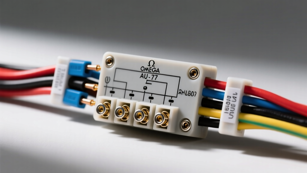
Introduction to the Omega AU 7 Relay System
When installing high-draw auxiliary lighting, dual-circuit light bars, or smart trailer bypass modules, standard 4-pin or 5-pin ISO relays often fall short. The Omega AU 7 relay wiring diagram outlines a specialized 7-pin heavy-duty relay module designed to handle complex automotive lighting loads while providing isolated trigger circuits and EMI (Electromagnetic Interference) shielding. Unlike basic automotive relays, the AU 7 series incorporates dual Normally Open (NO) outputs, a Normally Closed (NC) indicator circuit, and a dedicated logic ground to prevent voltage backfeed into sensitive CAN-bus systems.
Troubleshooting this specific 7-pin configuration requires a systematic approach. Jumping straight to replacing the relay without verifying the trigger logic or load-side voltage drops can lead to misdiagnosed faults, melted harnesses, or blown ECU drivers. This step-by-step troubleshooting flow will guide you through diagnosing the Omega AU 7 relay wiring diagram using a digital multimeter (DMM), ensuring your auxiliary lighting system operates reliably under extreme automotive conditions.
Omega AU 7 Pinout Configuration & Wire Specifications
Before initiating the troubleshooting flow, you must understand the specific pin assignments. The Omega AU 7 utilizes a weather-sealed 7-cavity connector (typically compatible with TE Connectivity AMP Superseal 1.5 or Delphi Weather-Pack 630 series housings). Below is the definitive pinout reference for the AU 7 module.
| Pin | ISO/Std Label | Wire Color | AWG Size | Function & Circuit Role |
|---|---|---|---|---|
| 1 | 30 | Red | 10 AWG TXL | Main 12V+ Battery Feed (Fused at source) |
| 2 | 85 | Black | 16 AWG TXL | Electromagnetic Coil Ground |
| 3 | 86 | White | 18 AWG TXL | Trigger / Switch Input (12V+ or CAN signal) |
| 4 | 87 | Yellow | 12 AWG TXL | Primary Load Output (Normally Open) |
| 5 | 87b | Yellow/Red | 12 AWG TXL | Secondary Load Output (Normally Open) |
| 6 | 87a | Green | 18 AWG TXL | Normally Closed (NC) Indicator / Status Output |
| 7 | Shield | Braided/Bare | 20 AWG | EMI Logic Ground / Flyback Diode Return |
Step-by-Step Troubleshooting Flow
Follow this sequential diagnostic flow to isolate faults within the Omega AU 7 relay wiring diagram. Always begin with the power and ground circuits before testing the trigger or load sides.
Phase 1: Verify Main Power and Coil Ground (Pins 1 & 2)
The most common cause of total lighting failure is a voltage drop on the main feed or a floating ground on the coil circuit.
- Test Pin 1 (30): Set your DMM to DC Volts. Place the red probe on the Pin 1 terminal and the black probe on a known good chassis ground. You should read between 12.4V and 12.6V (engine off) or 13.8V to 14.4V (engine running). If voltage is below 11.5V, inspect the inline maxi-fuse and the ring terminal connection at the battery positive post. Ensure M6 terminal lugs are torqued to 8-10 Nm.
- Test Pin 2 (85): Switch your DMM to Ohms (Ω). Disconnect the relay harness to prevent parallel circuit readings. Measure resistance between the Pin 2 wire and the chassis ground. It should read less than 0.5 Ω. High resistance here indicates corrosion in the Weather-Pack cavity or a poor grounding eyelet.
Phase 2: Isolate the Trigger Circuit (Pin 3)
The AU 7 relay requires a clean 12V+ trigger signal at Pin 3 (86) to energize the internal electromagnetic coil. In modern vehicles with CAN-bus or PWM (Pulse Width Modulation) lighting circuits, a standard trigger wire may cause the relay to chatter or fail to latch.
- Verify Trigger Voltage: Reconnect the harness. With the auxiliary light switch activated, back-probe Pin 3. You must see a minimum of 11.0V.
- Check for PWM Interference: If your DMM reads fluctuating voltage (e.g., jumping between 4V and 12V), the vehicle's BCM is sending a PWM signal to check for bulb outages. Fix: Install a 1000µF 25V electrolytic capacitor in parallel with the trigger circuit, or use a dedicated CAN-bus signal decoder module before Pin 3.
- Coil Resistance Test: With the harness disconnected, measure resistance across the relay's internal coil by probing the male terminals for Pin 2 and Pin 3 on the relay body. A healthy Omega AU 7 coil will read between 65 Ω and 85 Ω. An infinite reading (OL) indicates an open internal coil winding; the relay must be replaced.
Phase 3: Inspect Load Outputs and Voltage Drop (Pins 4 & 5)
Pins 4 (87) and 5 (87b) deliver the heavy current to your light bar or trailer lighting. According to SAE J592 Automotive Lighting Standards, excessive voltage drop at the load will drastically reduce the lumen output of HID or LED arrays.
- Perform a Loaded Voltage Drop Test: Connect your lighting load. Turn the system on. Place your DMM red probe on Pin 1 (Battery Feed) and the black probe on Pin 4 (Primary Output). A healthy relay contact will show a voltage drop of less than 0.2V. If the drop exceeds 0.5V, the internal contacts are pitted or carbon-fouled, creating excessive heat.
- Verify Secondary Output (Pin 5): Repeat the voltage drop test on Pin 5 (87b). If Pin 4 operates but Pin 5 does not, and external wiring continuity is confirmed, the internal bifurcated contact bridge inside the relay has failed.
Phase 4: Logic Ground & EMI Shield Verification (Pin 7)
Pin 7 is unique to the AU series. It provides a dedicated return path for the internal flyback suppression diode and EMI shielding. If Pin 7 is left ungrounded or tied to a noisy chassis ground, the voltage spike generated when the relay coil de-energizes can backfeed into the vehicle's BCM, triggering ghost codes or resetting the infotainment system.
- Ensure Pin 7 is routed directly to a clean, dedicated ground bus or the negative battery terminal, bypassing standard chassis grounds shared with high-draw accessories like winches or air compressors.
- Consult TE Connectivity Automotive Relay Specifications for proper flyback diode orientation if you are splicing an external suppression diode into the harness.
Diagnostic Decision Matrix: Common Failure Modes
Use this matrix to quickly cross-reference your symptoms with proven diagnostic solutions based on Littelfuse Automotive Circuit Protection guidelines.
| Symptom | Probable Cause | Multimeter Test | Corrective Action |
|---|---|---|---|
| Relay clicks rapidly (chattering) | PWM trigger signal or voltage drop on Pin 86 | AC Volts on Pin 3 (Should be 0V) | Install PWM filter / CAN-bus decoder |
| Lights dim after 5 minutes of use | High resistance / carbon buildup on Pins 87/87b | Voltage drop across Pin 30 to 87 (>0.3V) | Replace Omega AU 7 relay module |
| BCM throws 'Bulb Out' DTC codes | LED light bar draws too little current for BCM monitoring | Measure Amp draw on Pin 87 (< 0.5A) | Install 6 Ω 50W load resistors in parallel |
| Relay gets extremely hot to touch | Overloaded circuit exceeding 30A continuous rating | Clamp meter on Pin 30 wire (>35A) | Split load across two relays or upgrade wiring |
Wire Gauge, Crimping, and Connector Best Practices
The reliability of the Omega AU 7 relay wiring diagram relies heavily on terminal crimp quality. Never use solder on automotive relay harness terminals; solder wicks into the wire insulation, creating a rigid point that will snap under engine bay vibration. Instead, use a proper ratcheting crimper (such as the Delphi 12094430 equivalent for Weather-Pack terminals) to achieve a gas-tight mechanical crimp.
For the 10 AWG and 12 AWG load circuits (Pins 1, 4, and 5), always specify TXL (Cross-linked Polyethylene) or GXL wire, which features a thin wall and high-temperature resistance up to 125°C. Seal all butt splices and ring terminals using 3M or Raychem dual-wall adhesive-lined heat shrink. The inner meltable adhesive layer prevents moisture wicking, which is the primary cause of green copper oxide corrosion in auxiliary lighting harnesses. Finally, ensure the 7-pin housing cavity seals (matte seals) are fully seated over the wire insulation before crimping to maintain the IP67 waterproof rating of the AU 7 connector assembly.