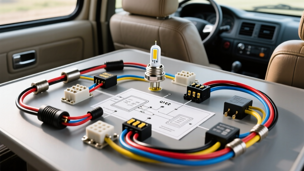
The 12V DC Paradigm Shift: Automotive & RV T12 LED Retrofits
For decades, 12V DC fluorescent T12 fixtures were the gold standard for illuminating enclosed car haulers, 5th-wheel toy haulers, horse trailers, and heavy-duty truck sleeper cabs. These fixtures relied on magnetic or electronic DC-to-DC ballasts to step up and regulate voltage for the fluorescent gas. Today, those ballasts are failing, and replacement parts are virtually obsolete. Upgrading to 12V DC LED T12 tubes is the most reliable solution, but it requires a precise bypass procedure.
When searching for a standard t12 ballast bypass led wiring diagram, most search results assume a 120V alternating current (AC) residential or commercial shop environment. However, in the automotive, RV, and heavy-transport sectors, we are dealing with 12V DC systems. Unlike AC current, where polarity alternates and standard T12 LED tubes can be wired without regard to positive/negative orientation, 12V DC LED tubes are diode-based. Polarity is absolute. Wiring a 12V DC LED tube backward will not simply fail to illuminate the tube; it can cause reverse-bias breakdown, melting the G13 tombstone sockets and creating a severe fire hazard in your rig or trailer.
This guide provides an expert-level, step-by-step troubleshooting flow and wiring methodology specifically tailored for 12V DC automotive and RV applications, adhering to NFPA 1192 (Standard on Recreational Vehicles) and SAE J1128 low-tension cable specifications.
12V DC T12 Ballast Bypass LED Wiring Diagram Logic
Before cutting a single wire, you must identify the internal driver configuration of your specific 12V DC LED replacement tubes. There are two primary configurations used in automotive and RV lighting:
- Single-Ended Power (SEP): One end of the tube is "Live" (contains the internal DC driver), and the other end is "Dead" (dummy pins for physical support). Both 12V+ and 12V- are fed into the same tombstone socket.
- Double-Ended Power (DEP): The internal driver spans the length of the tube. 12V+ is fed to one tombstone socket, and 12V- (Ground) is fed to the opposite tombstone socket.
G13 Socket & Polarity Matrix
| Tube Type | Socket A (End 1) | Socket B (End 2) | Polarity Requirement | Common Failure Mode |
|---|---|---|---|---|
| Single-Ended (SEP) | Pin 1: 12V+ (Red/Black) Pin 2: 12V- (White) |
Unwired (Dummy) | Strict DC Polarity | Short circuit if DEP wiring is applied |
| Double-Ended (DEP) | Both Pins: 12V+ (Red/Black) | Both Pins: 12V- (White) | Strict DC Polarity | Reverse bias diode failure if swapped |
Note: In standard RV and trailer 12V DC wiring, White is typically Ground (Negative) and Black or Red is 12V+ (Positive). However, always verify with a digital multimeter (DMM), as some vintage motorhome manufacturers inverted these color codes.
Step-by-Step Troubleshooting Flow (Decision Tree)
Use this diagnostic flow when a newly bypassed 12V DC T12 LED tube fails to operate correctly in your trailer or truck bay.
Symptom 1: Tube is Completely Dead (No Illumination)
- Check Polarity: Set DMM to DC Volts. Probe the tombstone socket pins. If you read -12V, your positive and ground are reversed. Fix: Swap the White and Black wires at the socket.
- Check for Dummy Socket Wiring: If using a Single-Ended tube, ensure you are testing the correct end. Fix: Rotate the tube 180 degrees or rewire the live socket.
- Verify Ballast Isolation: Did you cut the wires leading OUT of the old DC ballast, or just cap them? Fix: Physically remove the 12V DC ballast. Leaving it in the circuit can cause parasitic draw or feedback loops.
Symptom 2: Tube Flickers at Engine Idle (Alternator Ripple)
- Measure Voltage Drop: Probe the battery terminals, then probe the tombstone socket while the engine is idling. If the socket reads below 11.8V, you have excessive voltage drop. Fix: Upgrade the wiring from 14 AWG to 12 AWG stranded copper.
- Check for AC Ripple: Set DMM to AC Volts and probe the 12V DC socket. If you read more than 0.5V AC, your vehicle's alternator diode bridge is failing, or the LED driver lacks ripple rejection. Fix: Install a 1000µF 25V electrolytic capacitor in parallel at the socket to smooth the DC signal.
Symptom 3: Blown 5A ATO Fuse Upon Connection
- Inspect Tombstone Sockets: Older T12 fluorescent sockets often suffer from internal copper fatigue and arcing. When forced to carry the inrush current of an LED driver, they can short. Fix: Replace all G13 tombstone sockets with new, nickel-plated automotive-grade sockets.
- Check for Ground Faults: Ensure the exposed copper at the bypassed ballast is sealed with adhesive-lined heat shrink. Fix: Re-terminate all splices using a ratcheting crimp tool.
Execution: The 12V DC Bypass Procedure
Follow these steps to execute the bypass safely, ensuring compliance with RV Industry Association (RVIA) and automotive electrical best practices.
Step 1: Isolate and Remove the DC Ballast
Disconnect the negative terminal of the vehicle or RV house battery. Locate the 12V DC ballast (usually a heavy, potted rectangular block near the fixture). Cut the 12V+ and Ground wires feeding INTO the ballast, and the wires feeding OUT to the sockets. Remove the ballast entirely to eliminate dead weight and potential magnetic interference.
Step 2: Route and Terminate SAE J1128 Wiring
Do not use solid-core residential THHN wire. Automotive and RV environments are subject to high-frequency vibration. Use 14 AWG (or 12 AWG for runs over 10 feet) stranded copper wire meeting SAE J1128 specifications. Strip the wires and terminate them using adhesive-lined marine-grade heat shrink butt connectors. Apply heat until the adhesive oozes from the ends, creating a waterproof, vibration-proof seal.
Step 3: Wire the G13 Tombstone Sockets
For Double-Ended (DEP) tubes: Wire the 12V+ (Black/Red) to both pins on Socket A. Wire the 12V- (White) to both pins on Socket B. Bridge the two pins on each socket together using a short jumper wire to ensure equal current distribution and prevent arcing on a single pin.
For Single-Ended (SEP) tubes: Wire 12V+ to one pin and 12V- to the other pin on the "Live" socket. Leave the "Dead" socket completely unwired.
Step 4: Fuse Protection
LED tubes draw significantly less current than fluorescents, but inrush current can spike. Protect the circuit with a 5A ATO blade fuse located within 18 inches of the battery positive terminal or the main 12V DC distribution block. Never rely solely on the vehicle's 15A lighting circuit breaker, as it will not protect the 14 AWG fixture wiring from a localized short.
Voltage Drop & AWG Specification Chart (12V DC)
Voltage drop is the silent killer of 12V DC LED lighting. Because LEDs require a minimum threshold voltage to ignite the internal driver, a drop of even 1 volt over a long trailer run can cause flickering or failure to start.
| Wire Gauge (AWG) | Max Current (Amps) | Max Run Length (1 Tube / ~2A) | Max Run Length (4 Tubes / ~8A) |
|---|---|---|---|
| 16 AWG | 10A | 4 Feet | 1 Foot (Not Recommended) |
| 14 AWG | 15A | 10 Feet | 4 Feet |
| 12 AWG | 20A | 18 Feet | 8 Feet |
| 10 AWG | 30A | 30 Feet | 15 Feet |
Calculations based on a maximum allowable 3% voltage drop (0.36V) at 12.8V system voltage.
Final Inspection and Real-World Failure Modes
Before re-energizing the system, perform a continuity test between the 12V+ wire and the chassis ground to ensure no stray strands of copper are bridging the gap. A common real-world failure mode in enclosed auto haulers is the vibration-induced loosening of wire nuts. Never use wire nuts in automotive or RV applications. Always use crimped, heat-shrink-sealed terminals or WAGO lever-nuts secured to the chassis with a zip-tie mount.
By treating your 12V DC T12 LED retrofit with the same rigor as a chassis wiring harness, you ensure brilliant, flicker-free illumination for your cargo, trailer, or motorhome for years to come, completely eliminating the headache of failed DC fluorescent ballasts.