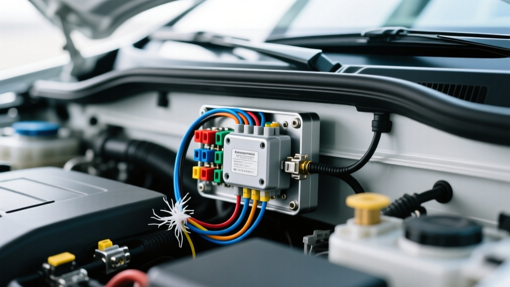
The Critical Role of a Relay Box for Cars in High-Draw Lighting
Upgrading to high-output LED light bars, HID headlight conversions, or heavy-duty auxiliary fog lamps requires more current than factory wiring harnesses can safely handle. Installing a dedicated relay box for cars is the industry-standard solution to isolate high-amperage loads from sensitive factory Body Control Modules (BCMs) and delicate dashboard switches. However, a poorly designed or incorrectly wired relay enclosure introduces severe fire hazards, voltage drop issues, and catastrophic electrical failures. As an automotive electrical specialist, I have diagnosed dozens of melted harnesses and failed lighting systems caused by fundamental installation errors. This guide details the most common mistakes made when wiring a relay box for cars and provides actionable safety warnings to ensure your auxiliary lighting system operates reliably and safely.
Mistake 1: Improper Main Fuse Placement and Sizing
The Hazard: Unprotected Power Feeds
The most dangerous mistake when wiring a relay box for cars is routing the main power feed from the battery to the relay box without proper overcurrent protection, or placing the fuse too far from the power source. According to Littelfuse Automotive Circuit Protection Guidelines, the primary fuse must be installed within 18 inches of the battery positive terminal. If a 10 AWG power wire chafes against the aluminum hood hinge or a steel firewall bracket before reaching a fuse block located inside the cabin, the wire becomes a dead short. The battery will dump hundreds of amps through the wire, melting the insulation and igniting a fire before the factory 120A main alternator fuse even thinks about blowing.
The Fix: Correct ANL and ATC Fusing
Always use a sealed, inline fuse holder or a dedicated distribution block mounted directly adjacent to the battery. For lighting setups drawing up to 30A, an ATC/ATO blade fuse is sufficient. For high-draw 50-inch light bars or dual fog light setups pulling 40A to 60A, you must step up to an ANL or MEGA fuse. Never use a fuse rated higher than the ampacity of the wire it protects; the fuse is there to protect the wire, not the load.
Mistake 2: Undersizing the Power and Ground Feed Wires
The Hazard: Voltage Drop and Thermal Runaway
Many DIY installers use 12 AWG or 14 AWG primary wire to feed a 40A relay box because it is flexible and easy to route. This is a critical violation of SAE J1128 Low Tension Primary Cable Standards. A 12 AWG copper wire is only rated for roughly 20A continuous current in an engine bay environment where ambient temperatures exceed 100°F (38°C). Pushing 35A through 12 AWG wire causes severe voltage drop. The lights will dim, the relay coil will chatter due to low voltage, and the wire insulation will eventually become brittle and crack from thermal runaway.
The Fix: Match AWG to Continuous Draw
Always size your wire based on the continuous draw of the lighting system, plus a 20% safety margin. Use stranded, cross-linked polyethylene (XLPE) insulated wire like TXL or GXL, which withstands high under-hood temperatures and resists abrasion far better than standard PVC wire. Furthermore, the ground wire returning to the chassis must be the exact same gauge as the positive feed wire. A bottleneck on the ground side will cause the same voltage drop and heating issues as an undersized positive feed.
Mistake 3: Misunderstanding Relay Pinouts and Coil Polarity
The Hazard: Back-EMF Spikes and CAN-Bus Damage
Standard ISO mini relays feature five pins: 30 (Common/Battery), 87 (Normally Open/Load), 87a (Normally Closed), 86 (Coil Positive), and 85 (Coil Negative). On a basic electromechanical relay, swapping pins 85 and 86 simply reverses the magnetic field, which is harmless. However, modern relay boxes for cars often utilize diode-suppressed or resistor-suppressed relays to protect sensitive CAN-bus networks from Back-Electromotive Force (Back-EMF). When a relay coil de-energizes, it generates a voltage spike that can exceed 100V. If you reverse the polarity on a diode-protected relay (applying 12V to pin 85 and Ground to pin 86), the internal flyback diode will short circuit, instantly destroying the relay and potentially back-feeding voltage into the BCM trigger circuit, frying the vehicle's computer.
The Fix: Verify Pin 86 and Pin 85 Orientation
Always read the schematic printed on the side of the relay. For diode-suppressed relays, Pin 86 MUST receive the +12V switched trigger from the dashboard switch or factory DRL module, and Pin 85 MUST go to a clean chassis ground. Use a digital multimeter (DMM) to verify trigger polarity before plugging the relay into the harness.
Mistake 4: Poor Grounding Practices and Daisy-Chaining
The Hazard: Stray Currents and Corrosion
A relay box for cars is only as reliable as its ground connection. A common mistake is daisy-chaining the grounds from multiple relays into a single small ring terminal, or attaching the ground to a painted suspension component or an aluminum engine bracket. Aluminum and steel have different galvanic potentials; connecting them with a copper wire and moisture creates a galvanic battery, leading to rapid corrosion and high resistance. High resistance on the ground side forces the electrical current to seek alternative paths back to the battery, often back-feeding through factory sensor grounds and causing erratic gauge cluster behavior.
The Fix: Star Washers and Dedicated Ground Points
Use a dedicated steel grounding point on the chassis. Remove all paint, powder coating, and rust using a wire wheel or sandpaper. Use a 3/8-inch closed-loop ring terminal, secured with a steel star washer to bite into the bare metal. Coat the terminal in dielectric grease or battery terminal protector spray to prevent oxidation. If your relay box has a centralized ground busbar, run a single heavy-gauge wire (e.g., 8 AWG) from the busbar to the chassis, rather than running individual ground wires from each relay.
Mistake 5: Soldering Instead of Crimping in High-Vibration Zones
The Hazard: Stress Risers and Wire Fractures
While soldering is excellent for stationary electronics, it is highly discouraged for automotive engine bay wiring. Solder wicks into the strands of the wire via capillary action, creating a rigid, inflexible section. In the high-vibration environment of an engine bay, the transition point between the flexible wire and the rigid soldered joint becomes a stress riser. Over time, engine harmonics will cause the copper strands to snap inside the insulation, leading to intermittent lighting failures or arcing inside the relay box.
The Fix: Gas-Tight Ratcheting Crimps
Use a high-quality ratcheting crimping tool designed for open-barrel or closed-barrel terminals (such as TE Connectivity CERTI-CRIMP or Delphi Weather-Pack specific tools). A proper crimp deforms the terminal and wire into a single, gas-tight mass that resists vibration and prevents oxygen from entering the joint to cause corrosion. Follow this up with an adhesive-lined dual-wall heat shrink tube to seal out moisture.
Relay Box Wire Gauge and Fuse Sizing Reference Chart
Use the following specification chart to properly size your power feeds, ground wires, and overcurrent protection when configuring your relay box for cars. These values assume a standard 12V-14V automotive electrical system and a maximum wire run of 15 feet (round trip).
| Max Continuous Draw | Recommended Relay | Feed Wire (AWG) | Ground Wire (AWG) | Main Fuse Type & Rating | Trigger Wire (AWG) |
|---|---|---|---|---|---|
| Up to 15A | 20A Mini ISO | 12 AWG TXL | 12 AWG TXL | 20A ATC Blade | 18 AWG |
| 16A to 25A | 30A Standard ISO | 10 AWG TXL | 10 AWG TXL | 30A ATC Blade | 16 AWG |
| 26A to 35A | 40A Heavy Duty ISO | 8 AWG TXL | 8 AWG TXL | 40A ANL / MEGA | 14 AWG |
| 36A to 50A | 60A Solenoid / Mega | 6 AWG TXL | 6 AWG TXL | 60A ANL | 12 AWG |
Troubleshooting Decision Tree: Relay Box Failures
When your auxiliary lighting fails to activate, use this structured diagnostic approach before replacing components:
- Symptom: Relay clicks rapidly or buzzes, lights flicker.
- Cause: Severe voltage drop on the trigger circuit or main power feed.
- Fix: Measure voltage between Pin 86 and Pin 85 while the switch is engaged. If it reads below 11.5V, check for undersized trigger wires, corroded dashboard switch contacts, or a poor ground at Pin 85.
- Symptom: Relay does not click, no power at Pin 87.
- Cause: Blown main fuse, broken coil wire, or reversed polarity on a diode-suppressed relay.
- Fix: Test for 12V at Pin 30. If present, apply direct 12V to Pin 86 and ground to Pin 85. If it still fails to click, the relay coil is internally open. Replace the relay.
- Symptom: Lights stay on after the ignition is turned off.
- Cause: Back-feeding from another circuit or using Pin 87a instead of Pin 87.
- Fix: Verify wiring diagram. Pin 87 is Normally Open (power flows only when energized). Pin 87a is Normally Closed (power flows until energized). Ensure your load is wired to Pin 87.
Final Safety Warnings for Automotive Relay Installations
Never use a relay box for cars to bypass factory safety interlocks, such as headlight DRL modules, airbag wiring, or ABS control modules. Tapping into CAN-bus data lines for trigger signals requires specialized solid-state relays or opto-isolators to prevent network corruption. Always disconnect the negative battery terminal before cutting, stripping, or crimping wires in the engine bay. Finally, ensure your relay enclosure is rated to at least IP67 for dust and water resistance; standard plastic project boxes without silicone gaskets will allow capillary moisture ingress, leading to galvanic corrosion on the 87 and 30 spades, ultimately causing high-resistance heating and melted relay sockets. For further reference on automotive electrical architecture and relay integration, consult the Bosch Mobility Solutions Electrical Architecture Documentation.