Introduction to Automotive Relay Switch Standards
A car relay switch is an electrically operated electromagnetic component designed to isolate high-current load circuits from low-current control circuits. In modern automotive lighting and accessory systems, relays prevent voltage drop, protect delicate OEM switchgear, and mitigate the risk of thermal fires in the wiring harness. The global automotive industry relies heavily on the ISO 7588 and DIN 72552 standards to dictate the physical dimensions, terminal numbering, and electrical tolerances of these components.
Whether you are upgrading a headlight circuit, installing an LED light bar, or troubleshooting a failing fog light system, understanding the exact technical specifications of your car relay switch is critical. This reference guide details the electrical parameters, pinout configurations, wire gauge requirements, and diagnostic procedures for standard ISO mini and micro relays.
DIN 72552 Terminal Pinout Configurations
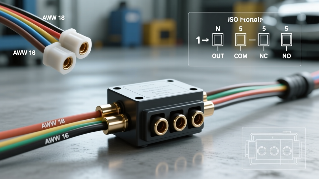
The DIN 72552 standard establishes a universal numbering system for automotive electrical terminals. This ensures that a car relay switch from any manufacturer will interface correctly with standardized ISO relay sockets. Below is the definitive pinout reference for the most common configurations.
| Pin Number | Function | Typical Aftermarket Wire Color | Technical Description |
|---|---|---|---|
| 30 | Common (COM) | Red (10 AWG) | Main power input directly from the battery or high-amperage bus bar. |
| 87 | Normally Open (NO) | Blue (10 AWG) | Output to the load (e.g., headlights, winch) when the coil is energized. |
| 87a | Normally Closed (NC) | White (10 AWG) | Output to the load when the coil is de-energized (5-pin relays only). |
| 86 | Coil Power (+) | Yellow (16-18 AWG) | Switched 12V input from the cabin switch, ECU, or BCM. |
| 85 | Coil Ground (-) | Black (16-18 AWG) | Ground path for the electromagnetic coil. |
4-Pin SPST vs. 5-Pin SPDT Architectures
A standard 4-pin car relay switch utilizes a Single Pole Single Throw (SPST) configuration. It acts as a simple remote-controlled on/off switch. When 12V is applied across pins 85 and 86, the electromagnetic coil pulls the internal armature down, bridging pin 30 to pin 87.
Conversely, a 5-pin relay uses a Single Pole Double Throw (SPDT) architecture. The addition of pin 87a (Normally Closed) allows for dual-circuit control. When de-energized, current flows from 30 to 87a. When energized, the connection to 87a is broken, and current flows from 30 to 87. This is frequently used in daytime running light (DRL) to headlight transition circuits or cooling fan override systems.
Electrical Specifications & Coil Ratings
Selecting the correct car relay switch requires matching the coil resistance and contact ratings to your vehicle's electrical system. Standard 12V automotive relays are engineered to operate within a specific voltage window to account for alternator output fluctuations.
| Specification Parameter | Standard 12V ISO Mini Relay | Heavy-Duty 12V Maxi Relay |
|---|---|---|
| Nominal Coil Voltage | 12V DC | 12V DC |
| Coil Resistance | 75 Ω ± 10% | 55 Ω ± 10% |
| Coil Power Consumption | ~1.8 Watts | ~2.6 Watts |
| Pull-In (Pick-Up) Voltage | ≤ 7.0V DC | ≤ 7.5V DC |
| Drop-Out Voltage | ≥ 1.5V DC | ≥ 1.8V DC |
| Max Continuous Contact Current | 30A - 40A | 50A - 70A |
| Max Inrush Current | 80A (for 10ms) | 120A (for 10ms) |
| Dielectric Strength | 500V AC (1 min) | 500V AC (1 min) |
The Role of Internal Suppression Resistors and Flyback Diodes
When the control circuit to a car relay switch is opened, the collapsing magnetic field in the coil generates a high-voltage reverse spike (inductive kickback). In older vehicles, this spike was harmless. However, in modern vehicles where the relay coil is driven by a Body Control Module (BCM) or Engine Control Unit (ECU) transistor, this spike can destroy the solid-state driver.
Many modern OEM relays feature an internal suppression resistor or a flyback diode wired in parallel with the coil. Critical Warning: If your car relay switch contains an internal flyback diode, the coil pins become polarity-sensitive. Pin 86 must be connected to the positive switched source, and pin 85 must be connected to ground. Reversing the polarity on a diode-protected relay will result in a short circuit, immediately blowing the control circuit fuse and potentially damaging the vehicle's ECU.
Wire Gauge (AWG) and Terminal Sizing Guidelines
Proper wire sizing is paramount to prevent voltage drop and thermal degradation. The load circuit (pins 30 and 87) carries the full amperage of the accessory, while the control circuit (pins 85 and 86) only carries the minor current required to energize the coil (typically 150mA to 200mA).
Load Circuit Sizing (Pins 30 & 87)
- Up to 20A: 12 AWG copper wire (Stranded, SXL or GXL insulation).
- 20A to 30A: 10 AWG copper wire. Standard for most fog light and headlight relay upgrades.
- 30A to 40A: 8 AWG copper wire. Required for high-draw LED light bars and auxiliary off-road lighting.
- Over 40A: 6 AWG or 4 AWG copper wire, paired with a heavy-duty Maxi relay.
Control Circuit Sizing (Pins 85 & 86)
- Standard Cabin Switch: 16 AWG wire is sufficient for runs under 10 feet.
- ECU/BCM Trigger: 18 AWG or 20 AWG wire. When tapping into an ECU driver, always use an add-a-circuit or proper military splice, and verify the ECU pin's maximum current output before connecting the relay coil.
Terminal Crimping Standards
Standard ISO mini relays utilize 0.250-inch (6.3mm) male spade terminals. For reliable connections, avoid using cheap closed-barrel crimpers. Instead, use an open-barrel crimping tool (such as the Deutsch DT or TE Connectivity AMP series) with heat-shrink adhesive terminals. The adhesive-lined heat shrink prevents moisture ingress and copper oxidation, which are the leading causes of high-resistance failures in under-hood lighting circuits.
Diagnostic Testing and Failure Modes
When a lighting circuit fails, the car relay switch is often the primary suspect. Use a digital multimeter (DMM) to perform the following diagnostic sequence.
Step 1: Coil Resistance Test
- Remove the relay from the socket.
- Set the DMM to the Ohms (Ω) setting.
- Place the probes on pins 85 and 86.
- Specification: A healthy 12V relay will read between 65Ω and 90Ω. A reading of 'OL' (Open Line) indicates a burnt internal coil wire. A reading near 0Ω indicates an internal short.
Step 2: Contact Continuity Test
- Set the DMM to the Continuity (beep) setting.
- Place probes on pins 30 and 87. The meter should read 'OL' (no continuity).
- Place probes on pins 30 and 87a (if 5-pin). The meter should beep (continuity present).
Step 3: Energized Load Test (Voltage Drop)
- Reinstall the relay and connect the load.
- Activate the circuit.
- Set the DMM to DC Volts.
- Place the positive probe on the battery positive terminal and the negative probe on pin 87's output wire.
- Specification: A voltage drop greater than 0.2V across the closed contacts indicates pitted, carbon-scored, or degraded internal contacts. The car relay switch must be replaced.
Authoritative References
For further engineering data, OEM integration parameters, and advanced solid-state relay specifications, consult the following industry standards and manufacturer resources:
- ISO 7588-1: Road Vehicles — Electrical/electronic switchgear — Relays - The definitive international standard for automotive relay dimensions, testing, and performance criteria.
- Littelfuse Automotive Relays Technical Catalog - Comprehensive datasheets on coil resistance, inrush current tolerances, and contact materials for ISO mini and micro relays.
- Bosch Automotive Relays and Switchgear Data - Historical and modern reference for DIN 72552 terminal numbering and heavy-duty switching architectures.