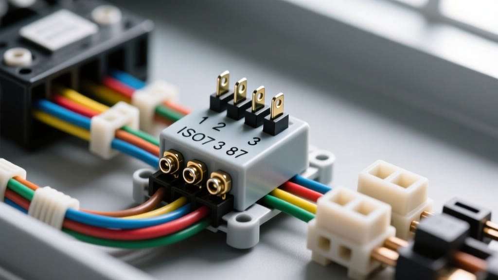
Critical Safety Warnings Before You Check Car Relay Circuits
When aftermarket lighting fails, headlamps flicker, or a light bar refuses to power on, the relay is the prime suspect. However, knowing how to check car relay components safely requires far more than simply swapping parts or jumping terminals with a screwdriver. Automotive electrical systems, particularly those integrated with modern Body Control Modules (BCMs) and CAN-bus networks, are highly sensitive to improper diagnostic procedures.
Before you unplug a single connector or touch a multimeter probe to a terminal, you must observe strict safety protocols. According to AA1Car's relay diagnostic guidelines, improper testing methods are responsible for a significant percentage of secondary electrical failures in modern vehicles. A single mistake can fry a $1,200 BCM, trigger an SRS airbag fault, or cause an under-hood electrical fire.
The Danger of Incandescent Test Lights on BCM Circuits
Never use a standard incandescent test light to probe the control circuit (Pins 85 and 86) on modern vehicles. An incandescent test light draws between 250mA and 500mA of current to illuminate the bulb. If the relay coil is ground-switched by a BCM or ECU logic driver, that driver transistor is typically only rated for a maximum of 200mA to 300mA. Forcing an incandescent test light into the control circuit will instantly overload and destroy the BCM driver. Always use a high-impedance Digital Multimeter (DMM) or a high-impedance LED test light that draws less than 10mA when checking car relay control signals.
Avoid SRS Airbag Harness Proximity
Automotive wiring standards (such as SAE J2972) dictate that all Supplemental Restraint System (SRS) airbag connectors and wiring are wrapped in yellow loom or feature yellow connector housings. When tracing relay wiring through the firewall bulkhead or under the dash, never backprobe or pierce yellow wires. A stray voltage spike from your multimeter or a short from a test probe can deploy an airbag or set a hard SRS crash code that requires dealer-level software to clear.
The 4 Most Dangerous Mistakes When Testing Relays
Even seasoned DIYers make critical errors when diagnosing lighting and relay circuits. Below are the most common mistakes that lead to misdiagnosed components, damaged harnesses, and severe fire hazards.
Mistake 1: Backprobing Weather-Pack Connectors with Paperclips
To check voltage at the relay socket, many technicians and hobbyists resort to bending paperclips or using oversized sewing needles to backprobe the rear of the connector. This is a catastrophic mistake. OEM lighting harnesses typically use Delphi Weather-Pack or Metri-Pack 280 terminals. These female terminals rely on precise beryllium-copper tension springs to maintain a gas-tight connection with the male relay blade.
Forcing a thick paperclip into the rear seal spreads the tension spring. Even if you get a voltage reading, you have permanently compromised the terminal. When you reinsert the relay, the loose connection will create high resistance. Under a 15A headlight load, this high resistance generates immense heat, eventually melting the ISO mini socket housing and causing an intermittent open circuit. Always use proper, thin-gauge T-pin backprobes designed specifically for automotive weather-sealed connectors.
Mistake 2: Ignoring Flyback Diode Polarity on Pins 85 and 86
The standard ISO Mini 4-pin relay (often referred to as a Bosch-style relay) features Pins 85 and 86 for the electromagnetic coil. In older vehicles, polarity did not matter; you could apply 12V to either pin and ground the other. However, as outlined in Hella's technical documentation on automotive relays, most modern OEM and high-quality aftermarket relays contain an internal flyback suppression diode or resistor to protect sensitive switching transistors from inductive voltage spikes when the coil de-energizes.
If you are testing a diode-protected relay and you reverse the polarity (applying 12V to the ground-side pin and grounding the 12V-side pin), you forward-bias the internal diode. This creates a dead short across the control circuit. The result? You will instantly blow the 10A or 15A ECU/BCM fuse, or worse, burn out the logic board trace inside the module. Always check the schematic printed on the relay housing for the diode symbol (a triangle with a line) to verify correct polarity before applying external power during a bench test.
Mistake 3: 'Hot-Wiring' Pin 30 Without an Inline Fuse
When trying to determine if a light bar or fog light assembly is functional, a common shortcut is to pull the relay, run a jumper wire directly from the battery positive terminal to Pin 30 (Common Power Input) in the socket, and bridge it to Pin 87. If you do this without an inline fuse, you are creating an unprotected, high-current circuit.
Pin 30 and Pin 87 circuits typically handle 20A to 40A loads and are wired with 12 AWG or 10 AWG wire. If your jumper wire accidentally brushes against the chassis, or if the lighting fixture has an internal short, the unfused 12 AWG wire will act as a heating element, melting its insulation and igniting nearby plastic or wiring loom within seconds. Never bypass the ATC/ATO blade fuse when jumping power to test a load circuit. Always use a fused jumper lead rated for the specific circuit amperage.
Mistake 4: Misdiagnosing Voltage Drop as a Bad Relay
Technicians often measure 12.6V at Pin 30, hear the relay click, but measure only 10.5V at Pin 87 (the output to the lights). They immediately condemn the relay as 'faulty contacts.' While carbon tracking on internal contacts is a real failure mode, the vast majority of the time, the relay is perfectly fine, and the issue is voltage drop on the wiring harness.
To properly check car relay load circuits, you must measure voltage drop under load. Set your DMM to DC Volts. Place the red probe on Pin 30 (battery feed side) and the black probe on Pin 87 (output side) while the relay is energized and the lights are drawing current. A healthy relay and socket will show a voltage drop of less than 0.2V. If you see a 1.5V drop across the relay, the internal contacts are indeed pitted. However, if you see 0.05V across the relay but the lights are still dim, the problem is undersized wiring (e.g., using 16 AWG wire for a 15A headlight circuit instead of the required 12 AWG) or corrosion at the chassis ground point, not the relay itself.
ISO Mini 4-Pin Relay Diagnostic Specification Chart
Use this reference table when diagnosing standard 4-pin ISO mini relays commonly used in headlight upgrades, fog light installations, and auxiliary light bar harnesses.
| Pin Number | Function | Typical Wire Gauge (AWG) | Expected Voltage (Energized) | Diagnostic Resistance / Notes |
|---|---|---|---|---|
| 30 | Common Input (Power Source) | 10 AWG to 12 AWG | 12.2V - 12.6V (Constant Battery) | Must have inline ATC fuse within 18 inches of battery. Check for bulkhead corrosion. |
| 87 | Normally Open (NO) Output | 10 AWG to 12 AWG | 0V (Off) / 12.0V+ (On) | Max allowable voltage drop across Pin 30 to 87 under load is 0.2V. |
| 86 | Coil Power (Switched 12V) | 16 AWG to 18 AWG | 12V+ when switch is activated | Coil resistance typically 65Ω - 90Ω. Verify polarity if diode-protected. |
| 85 | Coil Ground (Control Side) | 16 AWG to 18 AWG | 0V (Ground path completed) | If BCM controlled, do not use incandescent test light. Verify ground continuity < 0.5Ω. |
Proper Step-by-Step Bench Testing Procedure
If you suspect the relay itself is mechanically or electrically failed, remove it from the vehicle and perform a bench test. Refer to the Autometer relay wiring reference for standard bench testing configurations.
- Verify Coil Continuity: Set your DMM to Ohms (Ω). Place probes on Pins 85 and 86. You should read between 65 and 90 Ohms. If it reads OL (Open Line), the internal coil wire is broken. If it reads near 0 Ohms, the coil is shorted internally.
- Check for Diode Short: Swap your DMM probes between 85 and 86. If the relay has an internal suppression diode, you will see a high resistance reading in one direction and a low resistance (or voltage drop reading in diode-test mode) in the other. If it reads near 0 Ohms in both directions, the diode is shorted and the relay must be discarded.
- Load Test the Contacts: A relay might click audibly but fail to pass high amperage due to micro-corrosion on the copper contacts. Use a 30A power supply or a direct 12V battery source to energize the coil (85/86). Then, pass a known 10A load (like a 120W halogen work light) through Pins 30 and 87. Measure the voltage drop across the relay. If the drop exceeds 0.3V under a 10A load, the internal contacts are degraded and the relay is unsafe for automotive lighting use.
Final Thoughts on Relay Harness Integrity
Knowing how to check car relay circuits is only half the battle; maintaining the integrity of the connections is the other. Whenever you remove a relay for testing, inspect the male spades for signs of thermal fatigue (bluing or darkening of the metal) and check the female socket terminals for looseness. If the socket feels 'slippery' when inserting the relay, the harness pigtail must be cut out and replaced with a new, sealed ceramic or high-temp plastic connector. Always apply a small amount of dielectric grease to the relay spades before final insertion to prevent moisture ingress and galvanic corrosion, ensuring your lighting system operates safely for years to come.